MT3855G-G CONVEYOR OVENS INSTALLATION -- OPERATION -- MAINTENANCE MT3855G-G FOURS À BANDE TRANSPORTEUSE MANUEL D’INSTALLATION -- FONCTIONNEMENT -- ENTRETIEN BLODGETT OVEN COMPANY www.blodgettcorp.com 50 Lakeside Avenue, Box 586, Burlington, Vermont 05402 USA Telephone (800) 331-5842, (802) 860-3700 Fax: (802)864-0183 PN M5702 Rev D (6/01) E 2001 --- G.S.
IMPORTANT WARNING: IMPROPER INSTALLATION, ADJUSTMENT, ALTERATION, SERVICE OR MAINTENANCE CAN CAUSE PROPERTY DAMAGE, INJURY OR DEATH. READ THE INSTALLATION, OPERATING AND MAINTENANCE INSTRUCTIONS THOROUGHLY BEFORE INSTALLING OR SERVICING THIS EQUIPMENT AVERTISSEMENT: UNE INSTALLATION, UN AJUSTEMENT, UNE ALTÉRATION, UN SERVICE OU UN ENTRETIEN NON CONFORME AUX NORMES PEUT CAUSER DES DOMMAGES À LA PROPRIÉTE, DES BLESSURES OU LA MORT.
THE REPUTATION YOU CAN COUNT ON UNE RÉPUTATION SUR LAQUELLE VOUS POUVEZ COMPTER For over a century and a half, The Blodgett Oven Company has been building ovens and nothing but ovens. We’ve set the industry’s quality standard for all kinds of ovens for every foodservice operation regardless of size, application or budget.
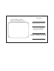
Model/Modèl: Your Service Agency’s Address: Adresse de votre agence de service: Serial Number/Numéro de série: Your oven was installed by/ Installateur de votre four: Your oven’s installation was checked by/ Contrôleur de l’installation de votre four:
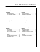
Table of Contents/Table des Matières Introduction Introduction Oven Description and Specifications . . . . 2 Description et Spécifications du Four . . . . 26 Oven Components . . . . . . . . . . . . . . . . . . . . 3 Éléments du Four . . . . . . . . . . . . . . . . . . . . . 27 Installation Installation Delivery and Inspection . . . . . . . . . . . . . . . 4 Livraison et Inspection . . . . . . . . . . . . . . . . 28 Oven Location and Ventilation . . . . . . . . . .
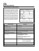
Introduction Oven Description and Specifications Cooking in a conveyor oven differs from cooking in a conventional deck or range oven since heated air is constantly recirculated over the product by a fan in an enclosed chamber. The moving air continually strips away the layer of cool air surrounding the product, quickly allowing the heat to penetrate. The result is a high quality product, cooked at a lower temperature in a shorter amount of time.
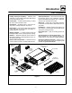
Introduction Oven Components Return Air Diverters --- divert return air from baking chamber back to the combustion chamber. Ensure even baking throughout oven. Located inside the oven, beneath the nozzles. Folding Conveyor Assembly --- stainless steel chain link (conveyor) belt and support that carries product through the oven. Control Box --- contains electrical wiring, cooling fan, drive motor and drive chain. End Plugs --- keep heat in the baking chamber.
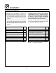
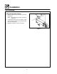
Installation Delivery and Inspection The Blodgett Oven Company cannot assume responsibility for loss or damage suffered in transit. The carrier assumed full responsibility for delivery in good order when the shipment was accepted. We are, however, prepared to assist you if filing a claim is necessary. All Blodgett ovens are shipped in containers to prevent damage. Upon delivery of your new oven: D D Inspect the shipping container for external damage.
Installation Oven Location and Ventilation LOCATION VENTILATION The well planned and proper placement of your oven will result in long term operator convenience and satisfactory performance. On gas models the necessity for a properly designed and installed ventilation system cannot be over emphasized. This system allows the oven to function properly while removing unwanted vapors and products of combustion from the operating area.
Installation Oven Assembly OVEN SUPPORTS AND CASTERS 1. Bolt the supports to the oven with 3/8-16 hex head bolts. NOTE: Install the locking casters on the front of the oven. 2. Carefully place the oven onto casters. Have several persons lift the oven off the pallet and set it onto the casters. 3. Engage the brakes on the front casters.
Installation Oven Assembly NOZZLES 1. Install the nozzles from center of the oven working towards the ends. Make sure the bottom of the air nozzle fits into the slot in the nozzle support located at the front of the oven. See Figure 5 for correct nozzle location. 2. Secure the nozzle hold-down strip across the inside front of the oven using the existing screws located on the oven wall. RETURN AIR DIVERTERS 1. Lift the front end of the diverter and slide the clips up and behind the oven’s rear wall. 2.
Installation Oven Assembly FOLDING CONVEYOR The folding conveyor assembly must be installed from the control box side of the oven. 1. Unfold the right side of the conveyor. 2. Push the conveyor into the support tracks. See Figure 6. Be careful to avoid hitting the red emergency off switch on the side of the control box. 3. Unfold the left side of the conveyor and continue to push into the support tracks. 4. Insert the conveyor in beyond the normal resting position. 5.
Installation Oven Assembly CRUMB PANS 1. Install the crumb pans under each end of the conveyor as shown in Figure 11. END PLUGS 1. Install the upper end plugs on both ends of the oven. See Figure 9. Secure the upper end plugs with two wing nuts on the bottom of each plug. Figure 11 REMOTE COMPUTER CONTROL 1. Drill the mounting holes for the cooking computer support base. 2. Mount the support base and cable support bracket to the wall. 3. Stack the cooking computer(s) on the support base.
Installation Utility Connections --- Standards and Codes THE INSTALLATION INSTRUCTIONS CONTAINED HEREIN ARE FOR THE USE OF QUALIFIED INSTALLATION AND SERVICE PERSONNEL ONLY. INSTALLATION OR SERVICE BY OTHER THAN QUALIFIED PERSONNEL MAY RESULT IN DAMAGE TO THE OVEN AND/OR INJURY TO THE OPERATOR.
Installation Gas Connection GAS PIPING A properly sized gas supply system is essential for maximum oven performance. Piping should be sized to provide a supply of gas sufficient to meet the maximum demand of all appliances on the line without loss of pressure at the equipment. Example: NOTE: BTU values in the following example are for natural gas. You purchase a MT3855G-G conveyor oven to add to your existing cook line. 1. Add the BTU rating of your current appliances.
Installation Gas Connection PRESSURE REGULATION AND TESTING MT3855G-G ovens are rated at 150,000 BTU/Hr. (43.9 kW) (158 MJ) Each oven has been adjusted at the factory to operate with the type of gas specified on the rating plate attached to the left side of the control panel. Each oven is supplied with a regulator to maintain the proper gas pressure. The regulator is essential to the proper operation of the oven and should not be removed. It is preset to provide the oven with 3.5” W.C. (0.
Installation Gas Connection GAS HOSE RESTRAINT U.S. and Canadian installations If the oven is mounted on casters, a commercial flexible connector with a minimum of 3/4” (1.9 cm) inside diameter must be used along with a quick connect device. The connector must comply with the Standard for Connectors for Movable Gas Appliances, ANSI Z21.69 or Connectors For Moveable Gas Appliances CAN/CGA-6.
Installation Electrical Connection Before making any electrical connections to this unit, check that the power supply is adequate for the voltage, amperage, and phase requirements stated on the rating plate. NOTE: The rating plate is located on the control box. WARNING!! Incorrect single phase wiring will result in extensive damage to electrical components and possible fire in the control box. A wiring diagram accompanies this manual and is also attached inside the control box. U.S.
Operation Safety Information THE INFORMATION CONTAINED IN THIS SECTION IS PROVIDED FOR THE USE OF QUALIFIED OPERATING PERSONNEL. QUALIFIED OPERATING PERSONNEL ARE THOSE WHO HAVE CAREFULLY READ THE INFORMATION CONTAINED IN THIS MANUAL, ARE FAMILIAR WITH THE FUNCTIONS OF THE OVEN AND/OR HAVE HAD PREVIOUS EXPERIENCE WITH THE OPERATION OF THE EQUIPMENT DESCRIBED. ADHERENCE TO THE PROCEDURES RECOMMENDED HEREIN WILL ASSURE THE ACHIEVEMENT OF OPTIMUM PERFORMANCE AND LONG, TROUBLE-FREE SERVICE.
Operation Cooking Computer CONTROL DESCRIPTION PROGRAMMING 1. DIGITAL DISPLAY --- displays the time, temperature and controller related information. 2. OVEN ON/OFF --- controls power to the oven. 3. NUMERIC KEYS --- used to enter numbers in the programming mode. 4. CLEAR KEY --- clears the display if an error is made in the programming mode. 5. SET TEMP KEY --- press to view or program the temperature setpoint. 6. ACT TEMP KEY --- press to view the current oven temperature. 7.
Operation Cooking Computer OPERATION DISPLAY INFORMATION To turn the oven on: WAIT D LOW --- the present oven temperature is lower than the set point temperature. When the oven reaches the set point temperature the display changes to READY. 1. Turn the manual gas valve to ON. (Gas models only) 2. Press and hold the ON/OFF key (2). The display reads OFF when the oven is idle. 3. The STATUS LAMPS (9) light. The fans begin to run. The heat rises to the temperature setting stored in the computer’s memory.
Operation Oven Adjustments for Cooking The combination of belt time, oven temperature, and air flow are important for achieving quality results from your Blodgett conveyor oven. Use the following guidelines to adjust the belt time and oven temperature of your unit. For questions regarding further oven adjustments, please contact your local Blodgett Sales Representative for assistance.
Maintenance Cleaning WARNING!! Always disconnect the power supply before cleaning or servicing the oven. WARNING!! If the oven needs to be moved, the gas must be turned off and disconnected from the unit before removing the restraint. Reconnect the restraint after the oven has been returned to its original location. Follow this recommended cleaning schedule for proper oven performance. Daily: 1. Clean the conveyor belt using a wire brush. Allow any foreign material to drop into the crumb pans. 2.
Maintenance Cleaning 4. Remove both lower end plugs. 5. Remove the conveyor assembly as follows: a.) Remove the 1/4” thumb screw holding the conveyor to the control box. b.) Slide the conveyor into the oven slightly. Remove the drive chain from the conveyor drive sprocket. c.) Slide the conveyor assembly out from the control box end. NOTE: Raise the far end of the conveyor to clear the conveyor guides. Handle the conveyor carefully to avoid pinching while folding. b.
Maintenance Cleaning 11. Move the oven to clean underneath. DO NOT damage the gas hose or electrical cords when moving. 12. Reverse steps 1---7 to reassemble. Be sure the diverters and nozzles are installed correctly. Refer to Figure 24. Inner Diverter Left Diverter Right Diverter Every 12 Months: A factory authorized service person should: 1. 2. 3. 4. Open and clean the inside of the control panel. Check and tighten all electrical connections. Check DC gear motor brushes for wear.
Maintenance Control Box Component Locations Cooling Blowers D.C. Control Board Air Flow Pressure Switch Control Circuit Breaker Burner Blower Head Module Control Power Supply And Relay Assembly Burner Blower Assembly Blower Circuit Breakers Burner Ignition Control Blower Motor Contactor Combination Pilot Valve Regulator D.C.
Maintenance Troubleshooting Guide POSSIBLE CAUSE(S) SUGGESTED REMEDY SYMPTOM: Blower motor(s) not running S S S S S S Computer Control turned OFF S S S S S S Emergency stop switch on OFF No power to oven Motor circuit breaker open Control Circuit breaker open Motor(s) burned out Press ON/OFF key Pull switch out to ON Reset breaker * * * SYMPTOM: Computer controller displays: Probe-Open-Probe-Short and alarm buzzer sounds S S S S Shorted or open RTD probe Computer controller not properly installed
Maintenance Troubleshooting Guide POSSIBLE CAUSE(S) SUGGESTED REMEDY SYMPTOM: Oven will not reach desired temperature S Gas pressure to oven is too low S S S S Top air plates missing S Temperature hi-limit system out of adjustment S S Internal problem with main temperature control S Check quick disconnect for proper seating Contact local gas representatives Install air plates * * SYMPTOM: Conveyor belt will not run S S S S S S Computer Control turned OFF S S S S S S Emergency stop switch on OFF Co
MT3855G-G Fours à Bande Transporteuse Manuel D’Installation --- Fonctionnement --- Entretien 25
Introduction Description et Spécifications du Four La cuisson dans un four à bande transporteuse diffère de la cuisson dans un four de cuisine ordinaire en ce sens que de l’air chaud circule en permanence autour de l’aliment cuit, sous l’effet d’un ventilateur enfermé dans une enceinte spéciale. Le mouvement continu de l’air, en éliminant constamment la couche d’air froid qui se formerait autrement autour de l’aliment, permet la pénétration plus rapide de la chaleur.
Introduction Éléments du Four Ensemble de la bande transporteuse repliable --- bande transporteuse, maillons de chaîne en acier inoxydable et support qui transportent le produit dans le four. Boîtier de commande --- contient les câblages électriques, ventilateur de refroidissement ou volets, moteur d’entraînement et chaîne d’entra”nement. Moteur d’entraînement --- fournit la puissance qui actionne la bande transporteuse.
Installation Livraison et Inspection Tous les fours sont expédiés en conteneurs. A la réception de votre four Blodgett vous devez: D D Vérifier que les emballages ne sont pas abimés. Toute défection dans l’emballage doit être notée sur l’accusé de reception de la marchandise; celui-ci doit être signé par le chauffeur. Sortir le four de son emballage et vérifier son bon état.
Installation Implantation et aération du four IMPLANTATION DU FOUR AÉRATION DU FOUR L’implantation correcte et bien étudiée du four sera à l’avantage à long terme de l’opérateur et permettra d’obtenir un rendement satisfaisant. On ne saurait trop insister sur la nécessité de prévoir un système d’aération bien conçu. Un tel système permettra au four de bien fonctionner, tout en évacuant les vapeurs et produits de combustion gênants de la zone d’utilisation.
Installation Montage du Four LES SUPPORTS DU FOUR ET LES ROULETTES 1. Boulonnez les supports du four à celui-ci au moyen de boulons de 3/8-16 à tête plate. NOTE: Les roulettes freinées doivent être tournées vers le devant du four 2. Faites reposer avec précaution le four sur les roulettes. Il sera nécessaire de le faire soulever de la palette et de le faire reposer sur les roulettes par plusieurs personnes. 3. Serrez les freins des roulettes avant. 4.
Installation Montage du Four DÉVIATEURS DE L’AIR EN RETOUR 1. Soulever l’avant du déviateur et glisser les attaches en haut et derrière la paroi de l’arrière du four. 2. Baisser l’avant et glisser le déviateur en place. Les déviateurs doivent être mis en place dans l’ordre correct. Voir Figure 4. NOTE: S’assurer que les bords des déviateurs de gauche et de droite s’alignent avec la découpe dans la paroi arrière du four. Déviateur gauche LES BUSES 1.
Installation Montage du Four BANDE TRANSPORTEUSE REPLIABLE L’ensemble de la bande transporteuse repliable doit être installé à partir du côté du boîtier de contrôle du four. 1. Déplier le côté droit de la bande transporteuse. 2. Pousser la bande transporteuse dans les rails de support. Voir Figure 6. Attention d’éviter de heurter l’interrupteur rouge d’arrêt d’urgence sur le côté du boîtier de contrôle. 3. Déplier le côté gauche de la bande transporteuse et continuer de pousser dans les rails de support. 4.
Installation Montage du Four LES ARRÊTOIR 1. Installez les arrêtoir supérieur aux deux extrémités du four. Voir Figure 9. Serrer les écrous à oreilles au bas de chaque arrêtor supérieur. PLATEAUX POUR MIETTES 1. Installez des plateaux pour miettes sous chaque extrémité de la bande transporteuse. Figure 11 Figure 9 2. Installez les arrêtoir inférieur aux deux extrémités du four. Voir Figure 10. L’ORDINATEUR DE CUISSON DÉTACHÉ 1.
Installation Branchements de Service --- Normes et Codes LES INSTRUCTIONS PORTANT SUR L’INSTALLATION ET CONTENUES DANS CE DOCUMENT, S’ADRESSENT UNIQUEMENT AU PERSONNEL D’INSTALLATION ET DE SERVICE QUALIFIÉ. TOUTE INSTALLATION OU SERVICE EFFECTUÉ PAR DU PERSONNEL NON QUALIFIÉ PEUT CAUSER DES DOMMAGES AU FOUR ET/OU DES BLESSURES À L’OPÉRATEUR.
Installation Branchement de Gaz CONDUIT DE GAZ Un système d’alimentation en gaz de bon calibre est essentiel pour obtenir le meilleur rendement du four. Les conduits doivent être calibrés pour fournir suffisamment de gaz pour alimenter tous les appareils sur le conduit sans perte de pression à l’équipement. Exemple: NOTE: Les valeurs en BTU de l’exemple suivant sont pour le gaz naturel. Achat d’un four à convection MT3855G-G qui doit être ajouté sur la conduite de cuisson existante. 1.
Installation Branchement de Gaz RÉGLAGE ET TEST DE PRESSION Chaque section du four MT3855G-G opère à régime nominal de 150,000 BTU/heure (43.9 kW) (158 MJ). Tous les fours sont réglés en usine en fonction du type de gaz spécifié sur la plaque signalétique. Cette plaque est fixée au côté gauche du panneau de commande. Pour maintenir la bonne pression de gaz, chaque four est livré avec un régulateur. Le régulateur est essentiel pour le fonctionnement correct du four et il ne doit pas être retiré.
Installation Branchement de Gaz RETENUE DU TUYAU DE GAZ Installations aux États-Unis et au Canada Si le four est monté sur roulettes, un connecteur commercial flexible ayant un diamètre intérieur minimum de 1,9 cm (3/4”) doit être utilisé avec un dispositif de connexion rapide. Le coupleur doit être conforme à la Norme Applicable aux Coupleurs pour Appareils à Gaz Mobiles, ANSI Z21.69 ou Coupleurs pour Appareils à Gaz Mobiles CAN/CGA-6.16.
Installation Raccordement Électrique Avant d’effectuer tout branchement électrique sur ces appareils, vérifiez que l’alimentation électrique est conforme aux spécifications de tension, d’intensité et de phase indiquées sur la plaque signalétique. NOTE: La plaque signalétique est fixée sur le panneau de commande. Un schéma de câblage, à coller sur la page prévue à cet effet, accompagne le présent manuel et est apposé à l’intérieur du boîte de commande.
Utilisation Informations de Sécurité LES INFORMATIONS CONTENUES DANS CETTE SECTION SONT DESTINÉES AU PERSONNEL QUALIFIÉ APPELÉ A UTILISER LE FOUR. ON ENTEND PAR PERSONNEL QUALIFIÉ LE PERSONNEL QUI AURA LU ATTENTIVEMENT LES INFORMATIONS CONTENUES DANS CE MANUEL, CONNAIT BIEN LES FONCTIONS DU FOUR ET/OU POSSEDE UNE EXPÉRIENCE ANTÉRIEURE DE L’EMPLOI DE L’ÉQUIPEMENT DÉCRIT.
Utilisation L’Ordinateur de Cuisson IDENTIFICATION DES COMMANDES LA PROCÉDÉ PROGRAMMER 1. AFFICHAGE - Indique la durée et la température, ainsi que d’autres informations relatives au fonctionnement du four. 2. MARCHE/ARRÊT --- Allume ou éteint le four. 3. CLAVIER NUMÉRIQUE --- Utiliser le clavier numérique pour programmer l’heure et la température de cuisson désirée. 4. TOUCHE CLEAR --- Utiliser le touche CLEAR en cas d’erreur. 5. TOUCHE SET TEMP --- Pour programmer ou consulter la temperature de cuisson.
Utilisation L’Ordinateur de Cuisson UTILISATION AUTRES MESSAGES DE L’AFFICHEUR Pour allumer le four WAIT D LOW --- la température du four est inférieure à celle programmée. Quand le four atteindra la température programmée l’afficheur indiquera READY (PRET). 1. Tourner la vanne de gaz sur MARCHE. 2. Appuyer et maintenir momentanément la touche MARCHE/ARRÊT (2). The display reads OFF when the oven is idle. 3. Les témoins lumineux VENTILATEUR et CHAUFFAGE (9) s’allumeront.
Utilisation Ajustements du Four Pour la Cuisson Le temps de la courroie, la température du four et la circulation d’air jouent un rôle important pour la qualité du produit final obtenu par les fours à convoyeur Blodgett. Utilisez les lignes directrices qui suivent pour ajuster le temps de passage de la courroie et la température du four de votre unité. Si vous avez des questions concernant les autres ajustements du four, veuillez contacter votre représentant local des fours Blodgett.
Utilisation Ajustements du four pour la cuisson Les exemples qui suivent illustrent la régulation de la circulation d’air. NOTE: La première moitié de la chambre du four a une grande influence sur la cuisson des aliments, tandis que la seconde moitié influence plutôt le brunissement. D Vous avez établi un bon temps et une bonne température de cuisson, mais vous désirez un meilleur brunissement. Glissez une des plaques 43 D D de blocage pour découvrir une rangée de trous du côté de la sortie du four.
Entretien Nettoyage AVERTISSEMENT!! Débranchez le four de la prise de courant avant son nettoyage ou son entretien. AVERTISSEMENT!! Si le four doit être plus écarté du mur, l’alimentation en gaz doit être coupée et la canalisation débranchée du four avant d’enlever la chaîne. Celle-ci doit être utilisée pour empêcher d’exercer toute contrainte sur le coupleur de gaz. Il convient de respecter le programme de nettoyage recommandé ci-après pour obtenir un fonctionnement et des performances corrects.
Entretien Nettoyage 4. Retirer les deux arrêtoirs inférieurs. 5. Retirer l’ensemble de la bande transporteuse comme suit: a.) Retirer la vis à oreilles de 1/4 qui tient la bande transporteuse sur le boîtier de contrôle. b.) Glisser légèrement la bande transporteuse dans le four et retirer la chaîne d’entraînement du pignon d’entraînement de la bande transporteuse. c.) Glisser l’ensemble de la bande transporteuse hors de l’extrémité du boîtier de contrôle.
Entretien Nettoyage 9. Nettoyer les plateaux à miettes, remettre les déviateurs de retour d’air, buses, plaques de débit d’air et arrêtoirs dans un mélange d’eau chaude/détergent. Rincer à l’eau claire. Pour les nettoyages difficiles utiliser un produit de dégraissage ou de nettoyage de four pour gros travaux qui est sans danger pour l’aluminium. NOTE: NE PAS immerger les arrêtoirs. Ils contiennent un isolant. 10.
Entretien Emplacements des Composants du Boîtier de Commande Ventilateurs de refroidissement Carte commande C.C. Avertisseur de pression de circulation d’air Disjoncteur de contrôle Module tête de soufflante de brûleur Ensemble alimentation électrique et relais de contrôle Assemblage de soufflante de brûleur Disjoncteurs de soufflerie Boîtier d’allumage de brûleur Contacteur de moteur de soufflante Ensemble soupape pilote détendeur Moteur C.C.
Entretien Guide de Détection des Pannes CAUSE(S) PROBABLE(S) SUGGESTION SYMPTOME: Le ou les moteurs de ventilation ne fonctionnent pas S L’ordinateur de contrôle est en position OFF S Le mettre sur ON (Marche) (Arrêt) S Interrupteur d’arrêt d’urgence sur OFF (ARRÊT) S Le mettre sur ON (Marche) S Le four n’est pas alimenté S Remettre à zéro les coupe-circuits S Le disjoncteur du moteur est ouvert S Le disjoncteur du contrôle est ouvert S Le ou les moteurs sont grillés S * S * S * SYMPTOME: L’ordinate
Entretien Guide de Détection des Pannes CAUSE(S) PROBABLE(S) SUGGESTION SYMPTOME: Le brûleur refuse de s’allumer S Le contrôle est sur OFF (Arrêt) S Le mettre sur ON (Marche) S Interrupteur d’arrêt d’urgence sur OFF (ARRÊT) S Le mettre sur ON (Marche) S Le ou les moteurs de ventilation ne marchent S pas S Le contrôle n’est pas réglé à une température S Le régler à la température désirée supérieure à la température ambiante S S S S S S Le robinet à gaz à réglage manuel est fermé S S S S S S Contrôle
Entretien Guide de Détection des Pannes CAUSE(S) PROBABLE(S) SUGGESTION SYMPTOME: Le tapis du convoyeur ne veut pas se mettre en marche S Le disjoncteur du convoyeur est en position OFF S Le mettre sur ON (Marche) (Arrêt) S Interrupteur d’arrêt d’urgence sur OFF (ARRÊT) S Le mettre sur ON (Marche) S Disjoncteur du contrôle ouvert S * S Le tapis est accroché à quelque chose dans le S Arrêter le four OFF (Arrêt), décrocher et libérer le four tapis S Le moteur d’entraînement du convoyeur est S * défectue
INSERT WIRING DIAGRAM HERE PLACER SCHÉMA DE CÂBLAGE ICI