MARK V CONVECTION OVEN INSTALLATION -- OPERATION -- MAINTENANCE BLODGETT OVEN COMPANY www.blodgett.com 44 Lakeside Avenue, Burlington, Vermont 05401 USA Telephone (800) 331-5842, (802) 860-3700 Fax: (802)864-0183 PN 17561 Rev N (3/06) E 2003 --- G.S.
IMPORTANT WARNING: IMPROPER INSTALLATION, ADJUSTMENT, ALTERATION, SERVICE OR MAINTENANCE CAN CAUSE PROPERTY DAMAGE, INJURY OR DEATH. READ THE INSTALLATION, OPERATING AND MAINTENANCE INSTRUCTIONS THOROUGHLY BEFORE INSTALLING OR SERVICING THIS EQUIPMENT FOR YOUR SAFETY Do not store or use gasoline or other flammable vapors or liquids in the vicinity of this or any other appliance. The information contained in this manual is important for the proper installation, use, and maintenance of this oven.
THE REPUTATION YOU CAN COUNT ON For over a century and a half, The Blodgett Oven Company has been building ovens and nothing but ovens. We’ve set the industry’s quality standard for all kinds of ovens for every foodservice operation regardless of size, application or budget. In fact, no one offers more models, sizes, and oven applications than Blodgett; gas and electric, full-size, half-size, countertop and deck, convection, Cook’n Hold, Combi-Ovens and the industry’s highest quality Pizza Oven line.
Model: Your Service Agency’s Address: Serial Number: Your oven was installed by: Your oven’s installation was checked by:
Table of Contents Introduction Oven Description and Specifications . . . . . . . . . . . . . . . . . . . . . . . . . . . . . . . . Oven Components . . . . . . . . . . . . . . . . . . . . . . . . . . . . . . . . . . . . . . . . . . . . . . . 2 3 Installation Delivery and Location . . . . . . . . . . . . . . . . . . . . . . . . . . . . . . . . . . . . . . . . . . . . . Oven Assembly . . . . . . . . . . . . . . . . . . . . . . . . . . . . . . . . . . . . . . . . . . . . . . . . . . NSF Bolts . . . . . . . .
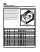
Introduction Oven Description and Specifications Cooking in a convection oven differs from cooking in a conventional deck or range oven since heated air is constantly recirculated over the product by a fan in an enclosed chamber. The moving air continually strips away the layer of cool air surrounding the product, quickly allowing the heat to penetrate. The result is a high quality product, cooked at a lower temperature in a shorter amount of time.
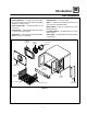
Introduction Oven Components Rack Supports --- hold oven racks. Heating Elements --- located on the back wall of the oven, the elements provide heat to the baking chamber on electric ovens. Baffle --- located on the back interior wall of the oven. Protects the blower wheel. Chain & Turnbuckle --- controls operation of the oven doors. Blower Wheel --- spins to circulate hot air in the baking chamber. Control Panel --- contains wiring and components to control the oven operation.
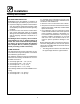
Installation Delivery and Location DELIVERY AND INSPECTION It is essential that an adequate air supply to the oven be maintained to provide a sufficient flow of combustion and ventilation air. All Blodgett ovens are shipped in containers to prevent damage. Upon delivery of your new oven: D D D Inspect the shipping container for external damage. Any evidence of damage should be noted on the delivery receipt which must be signed by the driver. Uncrate the oven and check for internal damage.
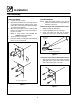
Installation Oven Assembly NSF BOLTS any holes in stacked units not used for mounting stacking brackets. 1. Locate the 5/16” bolts that were shipped with the oven. 2. Install the bolts as shown in Figure 3. D These bolts are required by NSF to block any exposed hole on the back of an oven. This includes: D any unit, single or stacked, without a back panel.
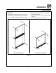
Installation Oven Assembly CASTER ASSEMBLY LEG ATTACHMENT 1. Lay the oven on its back. 2. Align the threaded stud in each leg with the nut located inside each bottom corner of the oven frame. Turn the legs clockwise and tighten to the nearest full turn. 3. Align the two leg plate holes in each leg with those in the oven bottom. Secure each leg using two 1/2” bolts. NOTE: If using casters see CASTER ASSEMBLY before proceeding. 4. Tip the oven up on the legs. 5.
Installation Oven Assembly DOUBLE SECTION ASSEMBLY 3. Attach the stacking brackets using the remaining 5/16” bolts shipped with the ovens. 4. Drill a clearance hole for a 5/16” bolt in the angle iron of the old style oven. Use the holes in the stacking brackets as a pilot. 5. Attach the stacking brackets to the old style oven with the 5/16” bolts and nuts provided in the kit. 6. Attach the flue connector. NOTE: Old style ovens refer to units with painted exposed rear angle.
Installation Utility Connections --- Standards and Codes U.S. and Canadian installations THE INSTALLATION INSTRUCTIONS CONTAINED HEREIN ARE FOR THE USE OF QUALIFIED INSTALLATION AND SERVICE PERSONNEL ONLY. INSTALLATION OR SERVICE BY OTHER THAN QUALIFIED PERSONNEL MAY RESULT IN DAMAGE TO THE OVEN AND/OR INJURY TO THE OPERATOR.
Installation Electrical Connection Wiring diagrams are located in the control compartment and on the back of the oven. The electric motor, indicator lights and related switches are connected to the oven as follows: Terminal Block 1. Remove the bottom trim and control panel covers. Slide the control panel forward. 2. Connect the supply conduit to the wire duct located in the lower left hand corner on the back of the oven. 3. Run the supply wires through the duct to the front of the oven. 4.
Installation Initial Startup OVEN RESTRAINT If casters are used in conjunction with a power supply cord for movable appliances, a fixed restraint should be provided. The restraint (ie: heavy gauge cable) should be attached without damaging the building. DO NOT use the gas piping or electrical conduit for the attachment of the permanent end of the restraint! Use anchor bolts in concrete or cement block. On wooden walls, drive hi test wood lag screws into the studs of the wall.
Operation Safety Information THE INFORMATION CONTAINED IN THIS SECTION IS PROVIDED FOR THE USE OF QUALIFIED OPERATING PERSONNEL. QUALIFIED OPERATING PERSONNEL ARE THOSE WHO HAVE CAREFULLY READ THE INFORMATION CONTAINED IN THIS MANUAL, ARE FAMILIAR WITH THE FUNCTIONS OF THE OVEN AND/OR HAVE HAD PREVIOUS EXPERIENCE WITH THE OPERATION OF THE EQUIPMENT DESCRIBED. ADHERENCE TO THE PROCEDURES RECOMMENDED HEREIN WILL ASSURE THE ACHIEVEMENT OF OPTIMUM PERFORMANCE AND LONG, TROUBLE-FREE SERVICE.
Operation Solid State Digital Control CONTROL DESCRIPTION 1. SELECTOR SWITCH --- turns power to the oven on or off. Allows selection of Cook or Cool Down Modes and fan speed (if applicable). 2. DISPLAY --- displays time or temperature and other information related to oven function. 3. HEAT LAMP --- lights when heater is on. 4. PULSE LAMP --- lights when Pulsed Fan Mode is turned on. 5. HOLD LAMP --- lights when Hold Mode is turned on. 6. DIAL --- used to enter set points in display 7.
Operation Solid State Digital Control OPERATION Cook with Pulse: Cook Only: NOTE: PULSE light is on when pulse mode is on and off when pulse mode is off. 1. Turn SELECTOR switch (1) to the desired position. 2. Enter the cook time and temperature. 3. Load product into oven. NOTE: The display reads LOAD with the oven is near the set temperature. 4. Press the START/STOP key (7). The timer begins to count down. 5. When the cook timer reaches 00:00 the buzzer sounds and the display reads DONE. 6.
Operation Solid State Manual Control CONTROL DESCRIPTION 1 1. SELECTOR SWITCH --- controls power to the oven for cook or cool down. 2. BLOWER SWITCH --- controls blower speed, either hi or lo. 3. LIGHTS SWITCH - controls interior lights. 4. OVEN READY LIGHT --- when lit indicates burner operation. When the light goes out the oven has reached operating temperature. 5.
Operation Blodgett IQ2T Control COMPONENT DESCRIPTION 1. OVEN POWER SWITCH --- controls power to the oven. 2. TOP DISPLAY --- displays temperature and other controller related information. 3. FAN HI LED --- when lit indicates the fan is running at high speed. 4. BOTTOM DISPLAY --- displays cook time and other controller related information. 5. PROG LED --- when lit indicates the controller is in the programming mode. 6. HEAT LED --- when lit indicates the control is calling for heat. 7.
Operation Blodgett IQ2T Control OVEN OPERATION Oven Startup: 1. Toggle the POWER SWITCH (1) to ON. The oven preheats to the lowest programmed first stage temperature. The LEDS (16) for all products with the same first stage temperature light. While the unit preheats the TOP DISPLAY (2) gives the set temperature. The BOTTOM DISPLAY (4) reads Lo if the oven is more than 10_ below setpoint. When the oven reaches ¦10_ of the preheat temperature an alarm sounds and the bottom display reads Ready.
Operation Blodgett IQ2T Control 3. Load the second product. Press the appropriate PRODUCT KEY (17). Press a SHELF KEY (18) to activate shelf timing. NOTE: Only products with lighted LEDS may be selected. 4. The top display reads SHLF. The bottom display gives the numbers of the shelves that have been assigned. Within five seconds the shelf with the least amount of time remaining is displayed. The led for the product with the least time remaining flashes faster than the led for the other products.
Operation Blodgett IQ2T Control PROGRAMMING SINGLE STAGE RECIPES Entering the Programming Mode: 1. Press and hold the PROG KEY (10). The top display reads CodE. 2. Use the product keys to enter the programming access code: 3 1 2 4. Press the ENTER KEY (14). The top display reads Prod. 3. Press the desired product key followed by the ENTER KEY (14). NOTE: During the programming process you may: Press the TOGGLE/CLEAR KEY (11) to erase the current setting or toggle between specific settings.
Operation Blodgett IQ2T Control Programming the Shelf ID: Programming Hold Mode: The Shelf ID option can be turned on or off for specific product keys. The hold mode can be toggled on or off for specific product keys. 1. The top display reads HOLD. The bottom display reads the current hold mode. Press TOGGLE/CLEAR KEY (11) to toggle between on and off. Press the SCAN KEY (15). 2. If the hold mode is activated, the bottom display give the current hold time. Press the TOGGLE/CLEAR KEY (11).
Operation Blodgett IQ2T Control PROGRAMMING MULTIPLE STAGE RECIPES Entering the Programming Mode: 1. Press and hold the PROG KEY (10). The top display reads CodE. 2. Use the product keys to enter the programming access code: 3 1 2 4. Press the ENTER KEY (14). The top display reads Prod. 3. Press the desired product key followed by the ENTER KEY (14). Programming the Cook Time: NOTE: When multiple stage cooking is being used, the countdown time displayed during cooking is the sum of all stages. 1.
Operation Blodgett IQ2T Control Programming the Fan Cycle Time: Programming the Timing Mode: There are 3 options for fan cycle time: Pulse, Heat and Full. Pulse allows the fan to turn on and off as programmed. Heat allows the fan to operate with heat only. Full provides continuous fan operation. NOTE: It may be necessary to press the ENTER KEY (14) until the top display reads tC ---1. 1. The top display reads CYC1. The bottom display gives the current fan cycle for stage 1.
Operation Blodgett IQ2T Control MANAGER LEVEL PROGRAMMING Programming the setback mode Entering the programming mode The setback mode operates as a power saving feature. After a period of non-use (the setback time) the oven temperature automatically decreases to the setback temperature. The oven will maintain this temperature until a product key is pressed. The minimum setback time is 20:00. 1. Press the PROG KEY (10). The top display reads CodE. 2.
Operation Blodgett IQ2T Control Programming the shelf sensitivity ERROR CODES AND ALARMS The controller allows the user to program a sensitivity value (0---9) for each shelf position. The sensitivity value will shorten or stretch cook time depending upon shelf position. NOTE: The error codes will appear in the top display. All error codes are accompanied by an audible alarm. Hi Oven temperature is more than 40_F above the highest setpoint.
Operation Cook and Hold Control CONTROL DESCRIPTION 1 1. SELECTOR SWITCH --- controls power to the oven for cook, cook & hold, and cool down. 2. WHITE LIGHTS SWITCH --- controls interior lights. 3. OVEN READY LIGHT --- when lit indicates burner operation. When the light goes out, the oven has reached operating temperature. 4. COOK THERMOSTAT --- controls oven temperature in the cook cycle. 5. COOK TIMER --- activates an electric buzzer that sounds when the cook time expires. 6.
Operation Cook and Hold Control OPERATION Cook Only: 1. Turn the SELECTOR SWITCH (1) to COOK. The blower and control compartment cooling fans operate and are controlled automatically by the action of the doors. 2. Set the COOK THERMOSTAT (4) to the desired temperature. 3. Preheat until the OVEN READY LIGHT (3) goes out. 4. Load product into the oven. Set the COOK TIMER (5) to the desired cook time. 5. When the buzzer sounds, remove the product. Turn the COOK TIMER (5) to OFF to silence the buzzer. 6.
Operation Pulse Plus CONTROL DESCRIPTION 1 1. SELECTOR SWITCH --- controls power to the oven for cook or cool down. 2. BLOWER SWITCH --- controls blower speed, either hi or lo. 3. WHITE LIGHTS SWITCH --- controls interior lights. 4. AMBER FAN DELAY LIGHT --- indicates the oven is in pulse plus. 5. FAN DELAY TIMER --- activates pulse plus for 0---10 minutes. The blower and burners pulse on for 30 seconds and off for 30 seconds for the duration of time set. 6.
Operation Humidaire CONTROL DESCRIPTION 1 1. SELECTOR SWITCH --- controls power to the oven for cook or cool down. 2. WHITE LIGHTS SWITCH --- controls interior lights. 3. OVEN READY LIGHT --- when lit indicates burner operation. When the light goes out, the oven has reached operating temperature. 4. SOLID STATE THERMOSTAT - allows either 8 pre-set temperatures to be selected in accordance with customer requirements, or an infinite selection of temperatures from 200-500_F (95-260_C).
Operation Intelliplus with Chain Event Control CONTROL DESCRIPTION 1. SELECTOR SWITCH --- controls power to the oven for cook or cool down. 2. OVEN READY LIGHT --- when lit indicates burner operation. When the light goes out the oven has reached operating temperature. 3. DIGITAL DISPLAY --- displays the time, temperature, and controller related information. 4. TIME DIAL --- used to set the cook and/or hold time of the selected program. 5.
Operation Intelliplus with Chain Event Control COOK OPERATION MANUAL COOK AND HOLD OPERATION 1. Rotate the TEMPERATURE dial (5) to the desired cooking temperature from 150-500_F (66-260_C). Turn the dial clockwise to increase the temperature, counter-clockwise to decrease. 2. Press the COOK HI/LO FAN key (8) until the display (3) reads HIFAN. Press the key again to select the low speed fan. The display reads LOFAN. 3. Press the FAN CON/CYC key (11) until the display reads FAN CON.
Operation Intelliplus with Chain Event Control CHAIN EVENT PROGRAMMING SELECTING A PROGRAM NOTE: Program keys 1 and 2 can have up to six events. Program keys 3-5 can have up to 4 events. 1. To select a program sequence, press the desired PGM # key (10). PGM # will be illuminated. At this time the oven begins to heat up to the cook temperature stored in the event #1 chain. EI is illuminated and the E1 options are displayed. The amount of time displayed is the sum total time of all the programmed events.
Operation How Cook and Hold Works With the optional COOK & HOLD feature, meat is roasted at lower temperatures for longer periods of time. This preserves flavor and tenderness and prevents over drying. There are three phases in cook and hold roasting. D D 225_ 200_ Primary Cooking --- controlled by the COOK & HOLD TIMER. The meat is cooked at a low temperature until approximately 2/3 done. Cooking from Stored Heat --- when the primary cook time expires, the oven automatically switches to HOLD.
Operation General Guidelines for Operating Personnel COOK TIMES AND TEMPERATURES OPERATING TIPS Preheating the oven Pans and Racks Always preheat the oven before baking or roasting. We recommend preheating 50_F (10_C) above the cook temperature to offset the drop in temperature when the doors are opened and cold product is loaded into the oven. Set the thermostat to the cook temperature after the product is loaded. Product or pan height determines how many racks are used.
Operation Suggested Times and Temperatures Product Temperature Time # Shelves Meats Hamburger Patties (5 per lb) Steamship Round (80 lb. quartered) Standing Rib Choice (20 lbs, trimmed, rare) Banquet Shell Steaks (10 oz. meat) Swiss Steak after Braising Baked Stuffed Pork Chop Boned Veal Roast (15 lbs.) Lamb Chops (small loin) Bacon (on racks in 18” x 26” pans) 400_F (205_C) 275_F (135_C) 235_F (115_C) 450_F (235_C) 275_F (135_C) 375_F (190_C) 300_F (150_C) 400_F (205_C) 400_F (205_C) 8-10 mins.
Maintenance Cleaning and Preventative Maintenance CLEANING THE OVEN PREVENTATIVE MAINTENANCE Painted and stainless steel ovens may be kept clean and in good condition with a light oil. 1. Saturate a cloth, and wipe the oven when it is cold. 2. Dry the oven with a clean cloth. The best preventative maintenance measures are, the proper installation of the equipment and a program for routinely cleaning the ovens.
Maintenance Troubleshooting Guide POSSIBLE CAUSE(S) SUGGESTED REMEDY SYMPTOM: Heating elements do not come on. S S S S S Oven not plugged in. S Power switch on the control panel is off. S Control set below ambient temperature. S Doors are open. S Computerized controls --- error code on display. S Plug in electrical supply cord. Set the control panel to COOK or OVEN ON. Set to desired cook temperature. Close doors. * SYMPTOM: Oven does not come to ready.
CUSTOMER INSERT WIRING DIAGRAM HERE