KLT-G Series GAS FIRED TRI-LEG TILTING KETTLE INSTALLATION – OPERATION – MAINTENANCE BLODGETT OVEN COMPANY IMPORTANT NOTES FOR INSTALLATION AND OPERATION www.blodgett.
It is recommended that this manual be read thoroughly and that all instructions be followed carefully. This is the safety alert symbol. It is used to alert you to potential personal injury hazards. Obey all safety messages that follow this symbol to avoid possible injury or death. FOR YOUR SAFETY: Do not store or use gasoline or other flammable vapors or liquids in the vicinity of this or any other appliance.
TABLE OF CONTENTS DESCRIPTION PAGE Important Notes For Installation and Operation 2 1.0 Service Connections 4 2.0 Installation 5 3.0 Operation 10 4.0 Cleaning Instructions 16 5.0 Maintenance 20 6.0 Service 21 7.
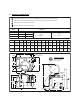
1.0 SERVICE CONNECTIONS Supply gas through 3/4" pipe . A gas shut-off valve must be installed in supply piping convenient and adjacent to appliance. Unless other wise specified, Field Wire Electrical Connection to be 120 Volts, 60 Hertz single phase with grounding wire. COLD WATER: 3/8"(10mm) tubing to faucet (OPTIONAL) HOT WATER: 3/8"(10mm) tubing to faucet (OPTIONAL) MODEL GAS SUPPLY BTU/HR. kW/HR. KLT-20G 80,000 23.4 KLT-40G 100,000 29.3 KLT-60G 120,000 35.2 SUPPLY PIPE PRESSURE (W.C.
2.0 INSTALLATION INSTALLATION CODES AND STANDARDS Installation must conform with local codes, or in the absence of local codes, with the National Fuel Gas Code, ANSI Z223.1/NFPA 54, or the Natural Gas and Propane Installation Code, CSA B149.1, as applicable. 1. The appliance and its individual shut off valve must be disconnected from the gas supply piping system during any pressure testing of that system at pressures in excess of ½ psi (3.5 kPa). . 2.
INSTALLATION (Continued) All units must be installed in such a manner that the flow of combustion and ventilation air are not obstructed. Provisions for an adequate air supply must also be provided. Do not obstruct side of the unit, as combustion air enters through this area. Information on the construction and installation of ventilating hoods may be obtained from the standard for “Vapor Removal from Cooking Equipment”, NFPA No.
2.0 INSTALLATION (Continued) GAS CONNECTION The serial plate on the lower right side of the unit indicates the type of gas your unit is equipped to burn. Do NOT connect to any other gas type. A 3/4" NPT line is provided at the rear for the connection. Each unit is equipped with an internal pressure regulator which is set for 3.5" W.C. manifold pressure for natural gas and 4.0" W.C. for propane gas. Use 1/8" pipe tap on the downstream side of the combination valve for checking pressure.
2.0 INSTALLATION (Continued) WATER CONNECTION On units equipped with an optional water fill valve connect a water line (minimum 1/4") to the valve with a 1/4" NPT female fitting. Units with dual (hot and cold) valves must have the hot water line connected to side with the hot water valve (red) and cold water line to the cold water valve (blue). Plastic or rubber hose is not recommended, as it may melt against the hot kettle side.
2.0 INSTALLATION (Continued) PERFORMANCE CHECK The following items should be checked before or within the first 30 days of operation by a qualified service technician. 1. Verify correct gas type against rating plate on unit. 2. Verify correct voltage, cycle and phase against rating plate on unit. 3. Gas pressure. 4. Internal gas connections. 5. Internal electrical connections. 6. Burners - adjustment and ignition. 7. Thermostat - cycle for operation check. 8. Gas supply valve - check for operation. 9.
3.0 OPERATION Contact the factory, the factory representative or a local service company to perform maintenance and repairs should the appliance malfunction. CAUTION: If you smell gas during the lighting procedure, immediately shut off the gas supply until the leak has been corrected. WARNING: In the event of main burner ignition failure, a 5 minute purge period must be observed prior to re-establishing ignition source.
3.0 OPERATION (Continued) A. Lighting (Continued) If after 36 seconds the burner fails to ignite or the “ignition light goes out, the system goes into Safety Lockout. De-energize the system by setting the thermostat to “OFF” for five minutes and try again. 1. Set the thermostat to desired temperature setting. When temperature setting has been reached, the “IGNITION” pilot will go off, turning off the burner. The unit will then cycle on and off to maintain set temperature.
3.0 OPERATION (Continued) FRONT PANEL CONTROLS POWER SWITCH This switch turns the main power to the unit on and off. It must be turned on to heat the kettle. It should be turned off when the kettle will not be in use for long periods. (GREEN) IGNITION LIGHT This light is on whenever the main burner gas is on. (RED) COOKING LIGHT This light is on when the thermostat is calling for heat. (AMBER) LOW WATER LIGHT All kettles are supplied with sufficient distilled water in pressurized jacket.
3.0 OPERATION (Continued) THERMOSTAT The thermostat selects the desired internal kettle operating temperature. The thermostat must be set at a desired setting in order for the burner to ignite. For Reference: DIAL SETTING EC EF 1 15 60 2 27 81 3 40 104 4 53 127 5 67 153 6 81 178 7 95 203 8 108 226 9 122 252 10 135 275 PRESSURE GAUGE The pressure gauge indicates the internal operating pressure of the kettle. When cold, the gauge should point to the green vacuum zone.
3.0 OPERATION (Continued) PRESSURE RELIEF VALVE The pressure relief valve is a safety device which prevents the internal kettle pressure from exceeding 50 psi. It should never be tampered with. DAILY OPERATION Daily operation should consist of turning on the power switch and setting thermostat for the desired temperature. It is recommended the kettle be preheated prior to use. Milk or egg based products should be placed in the kettle before heating however, to prevent sticking.
3.0 OPERATION (Continued) GAS SAVING TIPS Use these reminders to help develop energy-saving procedures and habits. Using less natural or propane gas saves energy as well as money. 1. Turn off when not in use. 2. Limit preheat times. 3. Use lid when possible. 4. Maintain equipment.
4.0 CLEANING INSTRUCTIONS WARNING: Disconnect the power supply to the appliance before cleaning or servicing. WARNING: Never spray water into electric controls or components! CAUTION: The equipment and its parts are hot. Use care when operating, cleaning and servicing. CAUTION: Do not use cleaning agents that are corrosive. Your kettle should be cleaned immediately after each use or when cooking a different product. Before cleaning, check that the kettle has cooled enough to touch it. 1.
4.0 CLEANING INSTRUCTIONS (Continued) DRAW-OFF VALVE CLEANING 1. If equipped with a tangent draw-off valve, turn the large hex nut on the draw-off valve counterclockwise until it is completely disengaged from the threads. Grasp the valve knob and slowly pull out the valve stem and disk. Do not allow the disk to come in contact with hard surfaces as it can be damaged and cause valve leakage. Wash the valve stem, disk and handle.
4.0 CLEANING INSTRUCTIONS (Continued) NOTICE: Draw-off valve has a vulcanized rubber coated stem for better sealing. Do not over tighten. This may cause the rubber to pull away from stem and permanently damage it. This is not covered under warranty. WHAT TO DO IF SURFACE RUST APPEARS Metal utensils should never be used as they will scratch the surface of the equipment and rust may begin to form.
4.0 CLEANING INSTRUCTIONS (Continued) Soil and burn deposits which do not respond to the above procedure can usually be removed by rubbing the surface with SCOTCH-BRITE™ scouring pads or STAINLESS scouring pads. DO NOT USE ORDINARY STEEL WOOL as any particles left on the surface will rust and further spoil the appearance of the finish. NEVER USE A WIRE BRUSH, STEEL SCOURING PADS (EXCEPT STAINLESS), SCRAPER, FILE OR OTHER STEEL TOOLS.
5.0 MAINTENANCE Contact the factory, the factory representative or a local service company to perform maintenance and repairs. WARNING: Disconnect the power supply to the appliance before cleaning or servicing. Daily: 1. Wash exposed cleanable areas. Monthly: 1. Blower wheel inlet and motor air vent should be cleansed if an accumulation of dust or lint is obvious. Twice a Year: (minimum) 1. Have an authorized service person clean and adjust the unit for maximum performance. 2.
6.0 SERVICE GENERAL When any difficulty arises always check that the unit has been connected to the gas supply type and voltage for which it was supplied. This can be done by examining the serial plate on the lower right side of the unit. It will list the gas type and voltage for which the unit was manufactured. Wiring diagrams for the unit are located in a small envelope affixed to the side panel of left hand console. Orifice Size Unit Total Input Natural Propane KLT-20G 80,000 BTU/Hour DMS # 19 (.
6.0 SERVICE (Continued) THERMOSTAT The thermostat adjustment should not be changed. Check the following before changing the thermostat. 1. With kettle cold, the pressure on the pressure gauge should read in the green vacuum zone (25 to 30 inches Hg vacuum). If not, see ‘Re-establishing Vacuum” section. 2. The pressure switch may be set too high or too low and causing the out of adjustment condition.
6.0 SERVICE (Continued) TO ADJUST PRESSURE SWITCH: 1. To obtain access to the pressure switch, the front panel must be removed. Remove the screws on bottom of the panel. Be sure to support the panel to avoid excessive strain on the wiring. 2. To increase the pressure switch setting, turn the white ribbed knob clockwise; to decrease, turn it counterclockwise. Use the centre of the black ring as an indicator. 3.
6.0 SERVICE (Continued) ADDING WATER (Low water light comes on) It may be necessary to replenish water in the jacket when the low water indicator comes on. Do so as follows: 1. Unit should be completely cold and off. 2. Lift handle of pressure relief valve to release vacuum in kettle. 3. Remove relief valve and attach a 3/4" NPT elbow pointing upward. 4. Using pure distilled water only, pour the water into the open end of elbow (a funnel will be helpful).
6.0 SERVICE (Continued) RE-ESTABLISHING VACUUM Periodically check pressure gauge when kettle is cold. Reading should be in green vacuum zone (below 0 psi). Otherwise air is present and proper heating will not occur. Use the following procedure to remove air and re-establish vacuum: With the kettle empty, turn the thermostat knob to the highest temperature. When the pressure gauge reaches 20 psi, turn thermostat off, open the pressure relief valve until pressure gauge reads 1 psi, then sharply release it.
7.0 TROUBLESHOOTING PROBLEM Motor will not run. S S S S S S S S S Motor runs, no spark. S S S S Motor runs, spark present, no gas ignition. S S S S LOOK FOR No current. Check that power is being supplied to the unit. Defective thermostat or pressure switch. Defective motor. Motor overload out. Blown fuse. Defective transformer. Defective ignition module. Blown fuse on ignition module. Defective spark electrode (cracked insulator). Defective ignition cable. Defective centrifugal switch on motor.
S S S S Flame burns only about 6 seconds and shuts off. S Flame rod or flame ground mislocated. Defective flame rod wire. Defective ignition module. Burner rate set too high. Ensure that manifold pressure is set per rating plate and that correct orifice size installed (See table page 21). Burner getting too much air. Reduce air shutter opening (not below 1.0). S Wrong size orifice. (See table on page 21). Low gas pressure. Air shutter adjustment.
Figure 1 Shutter setting at 2.
MATERIAL SAFETY DATA SHEET PREPARATION INFORMATION: Prepared for use in Canada by: E H & S Product Regulatory Management Department DOW CHEMICAL CANADA INC. P.O. Box 1012 Sarnia, Ontario, N7T 7K7 (800) 331-6451 1.
Product: DOWFROST* HD HEAT TRANSFER FLUID, DYED Product Code: 04632 Effective Date: 02/20/01, Date Printed: 07/10/02, MSD: 002239 3. HAZARDS IDENTIFICATION EMERGENCY OVERVIEW Clear yellow liquid. Odourless. Avoid temperatures above 450EF, 232EC. POTENTIAL HEALTH EFFECTS (See Section 11 for toxicological data.) EYE: May cause slight transient (temporary) eye irritation. Corneal injury is unlikely. Mists may cause eye irritation. SKIN CONTACT: Prolonged contact is essentially nonirritating to skin.
Product Code: 04632 Effective Date: 02/20/01, Date Printed: 07/10/02, MSD: 002239 4. FIRST AID EYES: Flush eyes with plenty of water. SKIN: Wash off in flowing water or shower. INGESTION: No adverse effects anticipated by this route of exposure incidental to proper industrial handling. INHALATION: Remove to fresh air if effects occur. Consult a physician. NOTE TO PHYSICIAN: No specific antidote. Supportive care. Treatment based on judgment of the physician in response to reactions of the patient.
MATERIAL SAFETY DATA SHEET Product: DOWFROST* HD HEAT TRANSFER FLUID, DYED Product Code: 04632 Effective Date: 02/20/01, Date Printed: 07/10/02, MSD: 002239 HAZARDOUS COMBUSTION PRODUCTS: During a fire, smoke may contain the original material in addition to unidentified toxic and/or irritating compounds. Hazardous combustion products may include and are not limited to carbon monoxide and carbon dioxide.
MATERIAL SAFETY DATA SHEET Product: DOWFROST* HD HEAT TRANSFER FLUID, DYED Product Code: 04632 Effective Date: 02/20/01, Date Printed: 07/10/02, MSD: 002239 6. ACCIDENTAL RELEASE MEASURES (See Section 15 for Regulatory Information) PROTECT PEOPLE: Use appropriate safety equipment. For additional information, refer to Section 8, Exposure Controls/ Personal Protection. PROTECT THE ENVIRONMENT: Avoid contamination of all waterways. CLEAN-UP: See Section 13, Disposal Consideration. 7.
MATERIAL SAFETY DATA SHEET Product: DOWFROST* HD HEAT TRANSFER FLUID, DYED Product Code: 04632 Effective Date: 02/20/01, Date Printed: 07/10/02, MSD: 002239 EXPOSURE GUIDELINES: Propylene glycol: AIHA WEEL is 50 ppm total, 10 mg/m3 aerosol only. 9. PHYSICAL AND CHEMICAL PROPERTIES APPEARANCE/PHYSICAL STATE: ODOUR: VAPOUR PRESSURE: VAPOUR DENSITY: BOILING POINT: SOLUBILITY IN WATER/MISCIBILITY: SPECIFIC GRAVITY OR DENSITY: Clear yellow liquid. Odourless 0.22 mmHg @ 20EC 2.6 320EF, 160EC Complete 1.
MATERIAL SAFETY DATA SHEET Product: DOWFROST* HD HEAT TRANSFER FLUID, DYED Product Code: 04632 Effective Date: 02/20/01, Date Printed: 07/10/02, MSD: 002239 SKIN: The LD50 for skin absorption in rabbits is >10,000 mg/kg. INGESTION: The oral LD50 for rats is 20,000 - 34,000 mg/kg. MUTAGENICITY: In vitro mutagenicity studies were negative. Animal mutagenicity studies were negative. 12.
MATERIAL SAFETY DATA SHEET Product: DOWFROST* HD HEAT TRANSFER FLUID, DYED Product Code: 04632 Effective Date: 02/20/01, Date Printed: 07/10/02, MSD: 002239 FOR UNUSED & UNCONTAMINATED PRODUCT, the preferred options include sending to a licensed, permitted: recycler, reclaimer, incinerator or other thermal destruction device.
MATERIAL SAFETY DATA SHEET Product: DOWFROST* HD HEAT TRANSFER FLUID, DYED Product Code: 04632 Effective Date: 02/20/01, Date Printed: 07/10/02, MSD: 002239 U.S. REGULATIONS SARA 313 INFORMATION: To the best of our knowledge, this product contains no chemical subject to SARA Title III Section 313 supplier notification requirements.
MATERIAL SAFETY DATA SHEET Product: DOWFROST* HD HEAT TRANSFER FLUID, DYED Product Code: 04632 Effective Date: 02/20/01, Date Printed: 07/10/02, MSD: 002239 CANADIAN REGULATIONS WHMIS INFORMATION: The Canadian Workplace Hazardous Materials Information System (WHMIS) Classification for this product is: This product is not a “Controlled Product” under WHMIS.