CTBRĆAP KFC ALL PURPOSE HALFĆSIZE ELECTRIC CONVECTION OVEN INSTALLATION - OPERATION - MAINTENANCE BLODGETT OVEN COMPANY www.blodgett.com 44 Lakeside Avenue, Burlington, Vermont 05401 USA Telephone: (802) 658Ć6600 Fax: (802)864Ć0183 PN 34532 Rev G (5/07) E 2007 - G.S.
IMPORTANT WARNING: IMPROPER INSTALLATION, ADJUSTMENT, ALTERATION, SERVICE OR MAINTENANCE CAN CAUSE PROPERTY DAMAGE, INJURY OR DEATH. READ THE INĆ STALLATION, OPERATING AND MAINTENANCE INĆ STRUCTIONS THOROUGHLY BEFORE INSTALLING OR SERVICING THIS EQUIPMENT FOR YOUR SAFETY Do not store or use gasoline or other flammable vapors or liquids in the vicinity of this or any other appliance. The information contained in this manual is important for the proper installation, use, and maintenance of this oven.
THE REPUTATION YOU CAN COUNT ON For over a century and a half, The Blodgett Oven Company has been building ovens and nothing but ovens. We've set the industry's quality standard for all kinds of ovens for every foodservice operation regardless of size, application or budget. In fact, no one offers more models, sizes, and oven applications than Blodgett; gas and electric, fullĆsize, halfĆsize, countertop and deck, conĆ vection, Cook'n Hold, CombiĆOvens and the industry's highest quality Pizza Oven line.
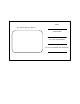
Model: Your Service Agency's Address: Serial Number: Your oven was installed by: Your oven's installation was checked by:
Table of Contents Introduction Oven Description and Specifications . . . . . . . . . . . . . . . . . . . . . . . . . . . . . . . . 2 Installation Delivery and Location . . . . . . . . . . . . . . . . . . . . . . . . . . . . . . . . . . . . . . . . . . . . . Utility Connections . . . . . . . . . . . . . . . . . . . . . . . . . . . . . . . . . . . . . . . . . . . . . . . Oven Assembly . . . . . . . . . . . . . . . . . . . . . . . . . . . . . . . . . . . . . . . . . . . . . . . . . . Stand Assembly . . . .
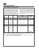
Introduction Oven Description and Specifications Cooking in a convection oven differs from cooking in a conventional deck or range oven since heated air is constantly recirculated over the product by a fan in an enclosed chamber. The moving air conĆ tinually strips away the layer of cool air surroundĆ ing the product, quickly allowing the heat to peneĆ trate. The result is a high quality product, cooked at a lower temperature in a shorter amount of time.
Installation Delivery and Location DELIVERY AND INSPECTION motor thermal overload protective device is caused by excessive ambient temperature on the control side of the oven resulting from insufficient ventilation. This condition must be corrected imĆ mediately to avoid permanent damage to the oven. All Blodgett ovens are shipped in containers to prevent damage. Upon delivery of your new oven: D D Inspect the shipping container for external damĆ age.
Installation Utility Connections ELECTRICAL CONNECTION THE INSTALLATION INSTRUCTIONS CONTAINED HEREIN ARE FOR THE USE OF QUALIFIED INĆ STALLATION AND SERVICE PERSONNEL ONLY. INSTALLATION OR SERVICE BY OTHER THAN QUALIFIED PERSONNEL MAY RESULT IN DAMĆ AGE TO THE OVEN AND/OR INJURY TO THE OPĆ ERATOR. WARNING!! Before making any utility connections to this oven, check the rating plate to be sure the oven specifications are compatible with the electrical services supplied for the oven.
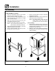
Installation Oven Assembly STAND ASSEMBLY 1. Place stand frame upside down on a work surĆ face. 2. Attach one leg to each of the corner stud bolts on the bottom of the stand top. 3. Place a lock washer and nut on each bolt and tighten. DO NOT tighten leg bolts completely. 4. Place the shelf between the legs so that the smooth top surface is facing the top of the stand. 5. Align the shelf holes with the bolt holes found near the bottom of each leg. 6.
Installation Oven Assembly OVEN ASSEMBLY TO STAND 1. Place the assembled stand in the location where the oven is going to be used. 2. Remove the side control compartment cover and open the front control panel of a single oven (or lower section). 3. With a tool, punch out the knockĆouts in the oven bottom near each corner. 4. Set the on the stand. Center it to the frame. NOTE: There should be approximately 1/2" of stand visible on all sides of the unit. 5.
Installation Oven Assembly DOUBLE SECTION ASSEMBLY There are three stacking configurations available for the CTBRĆAP. D D D See pages 8-10 for stacking instructions for all configurations.
Installation Oven Assembly Stacking two CTBRĆAP's or a CTB biscuit oven on top of a CTBRĆAP 5. Punch out the knockouts in the top of the lowĆ er section near the left hand corners. 6. Lay the upper section on its back. Attach the self adhesive gasket tape to the front and side edges on the bottom of the unit. See Figure 4. 7. Set the upper section on the lower section. 8. Align the front and rear bolt holes of the upper section with the bolt holes in the bottom section. 9.
Installation Oven Assembly Stacking a CTBRĆAP on top of a Mark V 1. Lay the Mark V on its back. 2. Remove the 25" legs. Pry the casters out of the old legs. 3. Attach the 6" legs with casters as follows: NOTE: The locking casters must be installed on the front of the oven. a.) Align the threaded stud in each leg with the nut located inside each bottom corner of the oven frame. Turn the legs clockwise and tighten to the nearest full turn. b.
Installation Oven Assembly View A Crown Trim Stacking Plate Top Cap Stacking Plate Stud Stud Gasket Tape See View A Attaching the Stacking Plate to the Mark V Attaching the CTBRĆAP to the Stacking Plate Figure 6 10
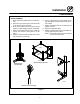
Installation Oven Assembly VENTILATION SINGLE OVENS 1. Mount the vent shield with the vent guard. Align the mounting holes in the vent shield with top holes in the vent guard. DOUBLE STACKED OVENS Two CTBRĆAP's or a CTB biscuit oven on top of a CTBRĆAP 1. Connect the upper and lower flues with the vent riser. Mount the vent shield with the vent riser. Align the mounting holes in the vent shield with top holes in the vent riser. Stacking a CTBRĆAP on top of a Mark V 1.
Operation Safety Information THE INFORMATION CONTAINED IN THIS SECĆ TION IS PROVIDED FOR THE USE OF QUALIFIED OPERATING PERSONNEL. QUALIFIED OPERATĆ ING PERSONNEL ARE THOSE WHO HAVE CAREFULLY READ THE INFORMATION CONĆ TAINED IN THIS MANUAL, ARE FAMILIAR WITH THE FUNCTIONS OF THE OVEN AND/OR HAVE HAD PREVIOUS EXPERIENCE WITH THE OPĆ ERATION OF THE EQUIPMENT DESCRIBED. ADĆ 12 HERENCE TO THE PROCEDURES RECOMĆ MENDED HEREIN WILL ASSURE THE ACHIEVEMENT OF OPTIMUM PERFORMANCE AND LONG, TROUBLEĆFREE SERVICE.
Operation IQ VVCĆ208 Control COMPONENT DESCRIPTION 1. Indicator Lights S Light up when product 2. Programming Buttons S Used to access programĆ 3. VFD (Vacuum Fluorescent Display) S Bright blue for easy viewĆ 4. SlideĆIn Menu Strips S Menu items are printed 5. Product Buttons S Used to activate cook 6. SCAN key S Used for recipe review key is activated. ming mode and change parameters. ing. Displays programming and cook cycle information. directly on easyĆtoĆ change menu strip.
Operation IQ VVCĆ208 Control OPERATIONAL TEST PROCEDURE 1 Plug oven into electrical source 2 Turn the oven power switch on. 3 NOTE: This scrolling can be bypassed by pressing SCAN. NOTE: AP and Mark V computer is unpowered if off. The XCEL is powered if plugged in. The controller will scroll through the following: a.) b.) c.) d.) e.) Appliance Type Software # Download # SCK Address PREHEAT" 4 The oven will enter PREHEAT" mode and begin to warm up.
Operation IQ VVCĆ208 Control SETBACK 1. Used to manually reduce the set temperature temporarily during times of infrequent cookĆ ing. Press the SETBACK key once to reduce the set temperature to the preĆprogrammed setback temperature. 2. Press the SETBACK key again to exit Setback and warm back up to the operating temperaĆ ture. PROGRAMMING Programming Mode for the Vision Controller is enĆ tered by pressing the P" key for three (3) secĆ onds.
Operation IQ VVCĆ208 Control CHANGING THE MENU STRIP 1 Turn off the oven power. 2 With a Phillips screwdriver, remove the two screws that secure the bezel of the VVCĆ208 in place. Remove the bezel. 3 Remove the existing menu strip(s) by lifting the tab and pulling the menu strip out from the bottom of the controller. 4 Using the tab as a guide, slide the new menu strip in. 5 Replace the bezel and screws that secure it to the controller. 6 Turn on the oven power.
Operation IQ VVCĆ208 Control RECIPE PROGRAMMING (1724) KEY PRESS DISPLAY ACTION S To enter programming mode, Enter Program mode press and hold the P" key for 3 seconds. S Scroll down to ProgramĆ 1 ming." S Press the P" key to lock in entry. S The display will prompt user to enter a pass code. Enter Pass Code S Enter pass code 1 7 2 4. S Press the P" key to lock in your entry. 2 RECIPE Choose a Product Key (Recipe) 3 ENTER CODE **** S Display will show Recipe." Press the P" key.
Operation IQ VVCĆ208 Control RECIPE PROGRAMMING (continued) KEY PRESS Choose a Product Name DISPLAY PRODUCT NAME 4 ACTION S Press the UP or DOWN arrow keys to scroll through product names, OR start spelling the desired product name by usĆ ing the top row of lettered product keys. S Press the P" key to lock in selection. Set Stage 1 Cook Time 5 STAGE 1 TIME MM:SS S Type in the time for Stage 1. Range is from 00:00 to 99:59. S Press the P" key to advance to next stage or parameter.
Operation IQ VVCĆ208 Control RECIPE PROGRAMMING (continued) KEY PRESS Set Stage 1 Fan Cycle DISPLAY STAGE 1 FAN CYCLE (FULL, HEAT, PULSE) ACTION S Press the LEFT or RIGHT arĆ row keys to select the fan cycle. S Press the P" key to advance 9 to next stage or parameter. Set Stage 1 Fan ON STAGE 1 FAN ON 9A NOTE: THIS SECTION ONLY APPEARS IF PULSE" IS SELECTED FOR FAN CYCLE. S Type in desired fan ON time. S Press the P" key to advance to next stage or parameter.
Operation IQ VVCĆ208 Control RECIPE PROGRAMMING (continued) KEY PRESS Set Alarm 1 Name (Selectable) DISPLAY ALARM 1 NAM ACTION" 12 ACTION S Press the UP or DOWN arrow keys to scroll through the Alarm Names, OR start spellĆ ing the desired action alarm name by pressing the apĆ propriate product keys. S Press P" key to lock in the selection. Set Alarm #1 Done Mode (selectable) ALARM 1 DONE (AUTOMATIC, MANUAL) row keys to select how the AcĆ tion Alarm is to be canceled.
Operation IQ VVCĆ208 Control RECIPE PROGRAMMING (continued) KEY PRESS Set Hold Done 18 DISPLAY HOLD DONE (AUTOMATIC, MANUAL) ACTION S Press the LEFT or RIGHT arĆ row keys to select how the hold alarm is to be cancelled. S Press the P" key to advance to the next step or parameter. Set Hold Fan Speed 19 HOLD FAN SPEED (HIGH, LOW) S Press the LEFT or RIGHT arĆ row keys to select the hold fan speed. S Press the P" key to advance to the next step or parameter.
Operation IQ VVCĆ208 Control SYSTEM PROGRAMMING (6647) KEY PRESS DISPLAY ACTION S To enter programming mode, Enter Program mode press and hold the P" key for 3 seconds. S Scroll Down to Programming. S Press the P" key to lock in 1 your entry. S The display will prompt user to enter a pass code. Enter pass code ENTER CODE **** S Enter pass code 6 6 4 7. S Press the P" key when SysĆ tem" is displayed. 2 S Press the P" key again to enĆ ter System Programming.
Operation IQ VVCĆ208 Control SYSTEM PROGRAMMING (continued) KEY PRESS Set Tone Level DISPLAY TONE LEVEL (None, 1, 2, 3, 4) 5 ACTION S Press the LEFT or RIGHT arĆ row keys to select a tone level. At each level the controller will continuously sound the seĆ lected tone. S Press the P" key to lock in your entry Set Temperature Mode TEMPERATURE F = FAHRENHEIT or C = CELSIUS 6 S Press the LEFT or RIGHT arĆ row keys to select the method that all temperatures will be displayed in.
Operation IQ VVCĆ208 Control SYSTEM PROGRAMMING (continued) KEY PRESS Set Hold Done 11 DISPLAY HOLD DONE (AUTOMATIC, MANUAL) ACTION S Press the LEFT or RIGHT arĆ row keys to select Hold Done. S Press the P" key to advance to the next stage or parameter. Set Hold Fan Speed 12 HOLD FAN SPEED (HIGH, LOW) S Press the LEFT or RIGHT arĆ row keys to select Hold Fan Speed. S Press the P" key to advance to the next stage or parameter.
Operation IQ VVCĆ208 Control PRODUCT OR ALARM NAME LIBRARIES (6647) KEY PRESS DISPLAY ACTION S To enter programming mode, Enter Program mode press and hold the P" key for 3 seconds. S Scroll Down to Programming. S Press the P" key to lock in 1 your entry. Enter Pass Code SYSTEM PROGRAMMING **** your entry. 2 PROD NAME LIB Or ALARM LIB 3 4 4A S Enter pass code 6 6 4 7. S Press the P" key to lock in S Scroll to Prod Name Lib" or Alarm Lib" S Press the P" key to advance.
Operation IQ VVCĆ208 Control PRODUCT OR ALARM NAME LIBRARIES (continued) KEY PRESS DISPLAY ACTION S Once name is located, press the SCAN key to toggle from predictive text input to tradiĆ tional text input. 4B S Use the LEFT and RIGHT arrow keys to move the cursor. S Press HOLD" to toggle beĆ 4C tween Upper and Lower case. S TEMP/TOGGLE CLEAR" can be used to clear the existing product name. S Press the P" key to complete.
Operation IQ VVCĆ208 Control SCK ADDRESS (6647) KEY PRESS DISPLAY ACTION S To enter programming mode, Enter Program Mode press and hold the P" key for 3 seconds. S Scroll to Programming. S Press the P" key. S The display will prompt user to 1 enter a pass code. Enter Pass Code ENTER CODE **** S Enter pass code 6 6 4 7. S Press the P" key to lock in your entry. 2 S Scroll to SCK Address. S Press P" to advance.
Operation IQ Control COMPONENT DESCRIPTION NOTE: The control version is indicated by symbols located at the bottom of the control. For exĆ ample: phase IV controls have squares. 1 1. OVEN POWER SWITCH - controls power to the oven. 2. TOP DISPLAY - displays temperature and other controller related information. 3. PROG LED - when lit indicates the controller is in the programming mode. 4. FAN HI LED - when lit indicates the fan is runĆ ning at high speed. 5.
Operation IQ Control OVEN OPERATION Multiple Batch Cooking Procedure: Oven Startup: This procedure is for single stage recipes with the same cook temperature and fan speed only. NOTE: If the led next to the first desired product key is lit skip step 1. NOTE: Press and hold the selected product key for three seconds to cancel the cook cycle. 1. Toggle the POWER SWITCH (1) to ON. Both disĆ plays read IN IT for approximately three secĆ onds.
Operation IQ Control 7. When the cook time expires an alarm sounds and the top display reads donE. The bottom display flashes 00:00. 8. Press the PRODUCT KEY (16) to silence the alarm. Remove the product. Using PreAlarms: 1. The top display reads AX__. NOTE: A indicates the alarm function. X is the prealarm number. __ is the alarm time. The LED for the active product key flashes. All othĆ er LEDS are off. The function keys are disabled. 2.
Operation IQ Control PROGRAMMING SINGLE STAGE RECIPES NOTE: Refer to the KFC Standards Library for acĆ tual recipes. Entering the Programming Mode: 1. Press the PROG KEY (9). The top display reads CodE. 2. Use the product keys to enter the programĆ ming access code: 3 1 2 4. Press the ENTER KEY (13). The top display reads Prod. 3. Press the desired product key followed by the ENTER KEY (13).
Operation IQ Control Programming the Timing Mode: There are 3 options for timing mode: Straight, Flex and Sensitivity. We recommend using the Flex mode. 1. The top display reads tC-1. The bottom disĆ play gives the current timing mode. Press the TOGGLE/CLEAR KEY (10) to toggle between St, FL and SEns. 2. If straight or flex are selected press the SCAN KEY (14) to advance the programming mode to PreAlarms. 3. If sensitivity is selected press the SCAN KEY (14) and continue with Steps 4-5.
Operation IQ Control PROGRAMMING MULTIPLE STAGE RECIPES NOTE: Refer to the KFC Standards Library for acĆ tual recipes. Entering the Programming Mode: 1. Press the PROG KEY (9). The top display reads CodE. 2. Use the product keys to enter the programĆ ming access code: 3 1 2 4. Press the ENTER KEY (13). The top display reads Prod. 3. Press the desired product key followed by the ENTER KEY (13). Programming the Cook Time: 1. 2. 3. 4. 5.
Operation IQ Control Programming the Fan Cycle Time: Programming the Timing Mode: There are 3 options for fan cycle time: Pulse, Heat and Full. Pulse allows the fan to turn on and off as programmed. Heat allows the fan to operate with heat only. Full provides continuous fan operation. We recommended using the Full fan cycle mode. NOTE: It may be necessary to press the ENTER KEY (13) until the top display reads tC-1. 1. The top display reads CYC1.
Operation IQ Control Programming the PreAlarms: A PreAlarm is an alarm that sounds during the cook cycle. PreAlarms can be used to alert the opĆ erator that the product needs to be turned or stirred, etc. Up to three PreAlarms can be proĆ grammed for each product. 1. The top display reads A1. The bottom display gives the alarm time. Use the product keys to enter the desired time for the first alarm. Press the ENTER KEY (13) to enter the PreAlarm time.
Operation IQ Control 2ND LEVEL PROGRAMMING Entering the programming mode 1. Press the PROG KEY (9). The top display reads CodE. 2. Use the product keys to enter the programĆ ming access code: 4 5 1 2. Press the ENTER KEY (13). The top display reads SYS. Programming hold Hold allows product to be kept warm in the oven at a programmed time and temperature. There are two hold modes available, auto and manual.
Operation IQ Control Programming the oven size ERROR CODES AND ALARMS 1. The top display reads APPL. The bottom disĆ play reads either FULL or HALF. Press the TOGGLE/CLEAR KEY (10) until the bottom display reads HALF for the CTBRĆAP. 2. Press the SCAN KEY (14) to enter the oven size and continue with exiting the programĆ ming mode. NOTE: The error codes will appear in the top disĆ play. All error codes are accompanied by an audible alarm.
Maintenance Cleaning and Preventative Maintenance CLEANING THE OVEN PREVENTATIVE MAINTENANCE Refer to KFC Equipment Standards Library VolĆ ume 2 - CTBRĆAP for morning startĆup and nightĆ ly cleaning procedures. The best preventative maintenance measures are the proper installation of the equipment and a proĆ gram for routinely cleaning the ovens. There are two critical performance areas that warĆ rant daily cleaning. These include: Annual Maintenance D D Fan Wheel Probe Cleaning the Fan Wheel 1.
ENDĆUSER LICENSE AGREEMENT FOR SCKR COMMUNICATION LINK SOFTWARE IMPORTANT - READ CAREFULLY: This is a leĆ gal agreement between the end user (YOU"), and Food Automation Service Techniques, Inc. (FAST"), the supplier of the SCKR CommunicaĆ tion Link Software (the SCKR Link Software") which is embedded within the controller of this apĆ pliance purchased from the BLODGETT OVEN COMPANY (COMPANY").
7. Limited Warranty: FAST WARRANTS THAT THE SCKR LINK SOFTWARE WILL, UNDER NORMAL AND ANTICIPATED USE, AND WHEN USED IN THE SPECIFIED OPERATĆ ING CONDITIONS, BE FREE FROM MATERIĆ AL OPERATING DEFECTS FOR TWO (2) YEARS FROM THE DATE OF PURCHASE. IF ANY CLAIM IS MADE THAT THE SCKR LINK SOFTWARE INFRINGES THIRD PARTY INĆ TELLECTUAL PROPERTY, FAST'S OBLIGAĆ TIONS SHALL BE EXCLUSIVELY SET FORTH IN 2Ć312(3) AND 2Ć607 OF THE CONNECTIĆ CUT UCC.