
Specifications


Operation
13
CTBR-AP Control
4
2
3
7
5
8
10
11
12
13
14
1
9
16
6
15
17
18
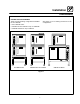
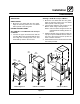
Figure 8
COMPONENT DESCRIPTION
NOTE: The con t rol ve rsio n is indicat e d by symbols
located at the bottom of the control. For ex-
ample: phase IV controls have squares.
1. OVEN POWER SWITCH --- controls power to
the oven.
2. TOP DISPLAY --- displays temperature and
other controller related information.
3. PROG LED --- when lit indicates the controller
is in the programming mode.
4. FAN HI LED --- when lit indicates the fan is run-
ning at high speed.
5 . B O T T O M D I S P L A Y --- d i s p l a y s c o o k t i m e a n d
other controller related information.
6. HEAT LED --- when lit indicates the control is
calling for heat.
7. FAN LO LED --- w hen lit indicates the fan is run-
ning at low speed.
8. COOL DOWN KEY --- press to enter the cool
down mode.
9. PROG KEY --- press to enter the programming
mode.
10. TOGGLE/CLEAR KEY --- press during pro-
gramming to toggle options or clear display.
11. ACT TEMP KEY --- press to display the actual
oven temperature.
12. SET TEMP KEY --- press to display the pro-
grammed cook temperature for the current
stage of the product k ey.
13. ENTER KEY --- press to enter new values into
product key programming. Also used to view
recovery time.
14. SCAN KEY --- completes the programming for
the current parameter and advances the con-
troller to the next parameter. Press to view t ime
remaining on multiple cook cycles.
15. PRODUCT LEDS --- when lit indicates which
product keys are currently in use or pro-
grammed for the current oven temperature
and fan speed.
16. PRODUCT K EYS --- assigns a key to a pro-
grammed recipe and begins a programmed
cooking process.
17. FUSE --- Provids oven circuit protection.
18. COMPORT --- used to download program-
ming information.