CB-G SERIES GAS STEAM BOILER CABINETS INSTALLATION – OPERATION – MAINTENANCE BLODGETT OVEN COMPANY www.blodgett.
IMPORTANT NOTES FOR INSTALLATION AND OPERATION It is recommended that this manual be read thoroughly and that all instructions be followed carefully. This manual should be retained for future reference. This is the safety alert symbol. It is used to alert you to potential personal injury hazards. Obey all safety messages that follow this symbol to avoid possible injury or death.
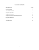
TABLE OF CONTENTS DESCRIPTION PAGE Service Connections 4 1.0 Installation Instructions 5 2.0 Service Connections 8 3.0 Operation Instructions 10 4.0 Operation Instructions for CSD1 Equipped Units 13 5.0 Periodic Maintenance 16 6.0 Adjustments 19 7.
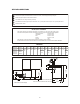
SERVICE CONNECTIONS Unless otherwise specified, Field Wire Electrical Connection to be 120 Volts, 60 Hertz single phase with grounding wire. DRAIN: 2"IPS piped to open floor drain. No Solid Connection. COLD WATER: 3/8" O.D. tubing at 25-50 PSI(170-345 kPa) GAS CONNECTION: 3/4"IPS supply line required. Natural Gas : min.7" (178mm) Water Column. Propane : min.11" (279mm) Water Column. S STEAM TAKE-OFF: 3/4"IPS.
GENERAL The gas boiler is designed to ASME Code and approved as a steam heating boiler restricted to operation at pressure not to exceed 15 psi. The gas boiler may be in a 24" cabinet base rated at 140,000 or 200,000 BTU, 36" cabinet base rated at 200,000, 250,000 or 300,000 BTU, operational on Natural or Propane gas. Boilers may have optional electronic ignition and CSD1 controls. 1.0 INSTALLATION INSTRUCTIONS UNPACKING Immediately after unpacking, check for possible shipping damage.
LEVELING AND ANCHORING THE CABINET 1. Place appliance in the installation position. 2. Place a carpenter’s level on top of the appliance and turn the adjustable feet to level side-to-side and front-to-back. 3. Mark hole locations on the floor through the anchoring holes provided in the rear flanged adjustable feet. 4. Remove appliance from installation position and drill holes in locations marked on the floor. Insert proper anchoring devices (not supplied). 5.
WARNING: ELECTRICAL GROUNDING INSTRUCTIONS This appliance is equipped with a three-prong (grounding) plug for your protection against shock hazard and should be plugged directly into a properly grounded three-prong receptacle. Do not cut or remove the grounding prong from this plug. (120V units only). WIRING DIAGRAM FOR APPLIANCE IS LOCATED INSIDE CABINET DOOR. EXHAUST FANS AND CANOPIES: Canopies are set over ranges, ovens, kettles, etc., for ventilation purposes.
2.0 SERVICE CONNECTIONS PLUMBING CONNECTIONS WARNING: Plumbing connections must comply with applicable sanitary, safety, and plumbing codes. WATER SUPPLY CONNECTION The incoming cold water supply connection, at the rear of the steamer cabinet, requires 3/8" tubing and water pressure of 25-50 psi. A manual shut-off valve must be provided convenient to the appliance; this valve should be open when the boiler is in operation.
Contact your gas company for correct supply line sizes. Purge the supply line to clean out any dust, dirt, or foreign matter before connecting the line to the unit. CAUTION: The pipe thread compound used when installing pipes must be a type that is resistant to the action of liquified petroleum or propane gases. Codes require that a gas shut-off valve be installed in the gas line prior to the steamer. Make sure the pipes are clean and free of obstructions, dirt, and piping compound.
3.0 OPERATION INSTRUCTIONS WARNING: Do not force the gas control knob. Use only your hand to turn the gas control knob. Never use any tool. If the gas control knob will not operate by hand the gas control should be replaced by a qualified service technician. WARNING: Do not disassemble the gas control; it contains no replaceable components. Attempted disassembly or repair may damage the gas control.
Safety Valve - This valve will release (pop off) if the boiler has too much pressure. Once a week, this valve should be tripped during operation to make sure it functions properly. START UP - BOILER OPERATION WITH STANDING PILOT IGNITION 1. Open manual gas shut off valve and if the appliance has a manual blowdown valve, close it. 2. Open cabinet door and turn ON power switch located on left side.
3. With the gas control valve, power switch and water supply all ON, water begins entering the boiler and gas flows to the pilot: Spark will begin in 2 to 3 seconds. If the pilot fails to light in 90 seconds, the control will provide 100% lockout. If this occurs: Wait 5 minutes, then turn power switch off for one minute before turning power switch back on. 4. Once the pilot is lit and the required water level has been reached, the main burners will ignite.
4.0 OPERATION INSTRUCTIONS FOR CSD1 EQUIPPED UNITS Initial Start-Up Procedure 1. Open the manual gas shut-off valve. 2. Close the manual blowdown valve, if so equipped. 3. Light the pilot burner. The dial on the combination gas valve has three positions (ON-OFF-PILOT) for manual gas control of main burners and pilot burner. Turn the dial to PILOT. Depress the dial and light the pilot burner on the center burner of boiler. Maintain the dial in depressed position for about 30 seconds and release.
Complete Shutdown Procedure If the appliance is not intended to be operational for a lengthy period of time, shut it down completely. 1. Open the manual blowdown valve, is so equipped. 2. Shut off all supplies of power, gas and water to the appliance. Normal Boiler Operating Cycle Water Fill Cycle On the initial filling of the boiler, the reset switch must be activated to initialize the safety lockout circuit.
Safety Lockout Conditions High Temperature Condition A high temperature safety device is installed on the boiler. Should the temperature exceed the limit of this device, the boiler will be shut down and be put in a state of lockout. The “Temperature” pilot light (Red), and the “Standby” pilot (amber), will come on. High Pressure Condition A high pressure safety switch is installed on the boiler.
5.0 PERIODIC MAINTENANCE Be sure to flush your boiler water level control daily. Failure to follow this procedure can cause the control to malfunction resulting in serious boiler damage. The Boiler Water Level Control installed on your boiler requires periodic maintenance. As boiler water circulates into the float chamber, sand, scale and other sediment may be deposited in the float chamber.
CAUTION: If burner does not shut off during blowdown, immediately discontinue use of appliance and call for service. Continue draining water for about fifteen (15) seconds, from control until water is clean. Manually close valve. Recheck gauge glass. If water level has dropped significantly, wait for the boiler to restore water level and pressure and repeat if necessary. WARNING: Disconnect the power supply to the appliance before cleaning or servicing. 1.
VENT HOOD Twice a year check the venting system (hood); remove any obstructions; and clean as necessary. BOILER DESCALING INSTRUCTIONS It is recommended that the boiler be checked every 90 to 120 days for scale build up. Regular maintenance should be carried out at this time. If the boiler is descaled, a new Anode should be installed in the boiler to help extend its life. 1. With boiler empty, close manual blowdown valve. If appliance is equipped with automatic blowdown, turn water supply OFF to appliance.
6.0 ADJUSTMENTS WARNING: At least twice a year have an authorized service person clean and adjust the unit for maximum performance. TO CALIBRATE PRESSURE SWITCHES NOTE: Pressure switches are factory set. Calibration is only required if pressure switches are replaced or if adjustment is required. Pressure switch range is from 1 to 15 psi. Adjust all settings to maximum on high signal adjustment screw on pressure switches. Adjust in the following sequence: - High limit pressure switch.
7.0 TROUBLESHOOTING WARNING: The boiler and its parts are hot. Use care when operating, cleaning, or servicing the boiler. BURNERS PRODUCE CARBON DEPOSITS 1. Wrong size orifices. 2. Burner air not adjusted properly. 3. Wrong gas supply. 4. Incorrect pressure at supply. PILOT DOES NOT LIGHT 1. Gas supply to unit is OFF. 2. Power supply is OFF. 3. Gas control knob is OFF. 4. Dirty or loose wire connection to module - clean and/or tighten. 5.
BURNER DOES NOT COME ON 1. Gas supply to unit is “OFF”. 2. Manual shut off valve is “OFF”. 3. Power supply is “OFF”. 4. Faulty valve or ignition module. 5. Pilot out. 6. Pilot may require flame adjustment. 7. Water level has not been reached in boiler. Check water supply is on, check water level control. 8. If water at proper level, check relay which energizes pressure switch and gas control. 9. Pressure switch may need to be replaced if relay is operating. 10.