CB-E SERIES ELECTRIC STEAM BOILER CABINETS INSTALLATION – OPERATION – MAINTENANCE BLODGETT OVEN COMPANY www.blodgett.
IMPORTANT NOTES FOR INSTALLATION AND OPERATION It is recommended that this manual be read thoroughly and that all instructions be followed carefully. This is the safety alert symbol. It is used to alert you to potential personal injury hazards. Obey all safety messages that follow this symbol to avoid possible injury or death. WARNING: Improper installation, operation, adjustment, alteration, service or maintenance can cause property damage, injury or death.
. TABLE OF CONTENTS DESCRIPTION PAGE 1.0 Service Connections ............................................................................................... 4 2.0 Installation Instructions ........................................................................................... 5 3.0 Operating Instructions ............................................................................................ 8 4.0 CSD-1 Optional Feature ............................................................................
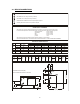
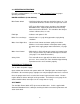
2.0 SERVICE CONNECTIONS DRAIN: 2"IPS piped to open floor drain. No Solid Connection. COLD WATER: 3/8" O.D. tubing at 25-50 PSI(170-345 kPa) HOT WATER: 3/8" O.D. tubing at 25-50 PSI(170-345 kPa) S STEAM TAKE-OFF CONNECTION: 3/4"IPS to operate adjacent equipment. Field Wiring Electrical Connection to be as specified on data plate. WATER QUALITY STATEMENT Water quality is the major factor affecting the performance of your appliance.
2.0 INSTALLATION INSTRUCTIONS GENERAL The electric boiler is designed to ASME Code and approved as a steam heating boiler restricted to operation at pressure not to exceed 15 psi. Boilers are electrically rated as shown on page 4. Boiler may have optional CSD1 controls. UNPACKING Immediately after unpacking, check for possible shipping damage. If the appliance is found to be damaged, save the packaging material and contact the carrier within 15 days of delivery.
LEVELING AND ANCHORING THE CABINET 1. Place appliance in the installation position. 2. Place a carpenter’s level on top of the appliance and turn the adjustable feet to level side-to-side and front-to-back. 3. Mark hole locations on the floor through the anchoring holes provided in the rear flanged adjustable feet. 4. Remove appliance from installation position and drill holes in locations marked on the floor. (See installation diagram on page 4.) Insert proper anchoring devices (not supplied). 5.
EXHAUST HOOD An exhaust system should be located directly above the boiler to exhaust steam and heat generated by the boiler. PLUMBING CONNECTIONS (See Page 4) WARNING: Plumbing connections must comply with applicable sanitary, safety, and plumbing codes. Water Supply Connection The incoming cold water supply connection, at the rear of the boiler cabinet, requires 3/8" tubing and water pressure of 25 - 50 psig.
3.0 OPERATING INSTRUCTIONS For CSD-1 equipped boilers, see section 4.0 CSD-1 Optional Feature for proper operating instructions. BOILER CONTROLS (Inside Cabinet) Main Power Switch - ON fills the boiler tank and turns the boiler heaters on. You should allow 20 minutes to fill the tank and generate steam. - OFF shuts off the boiler heaters and opens the Automatic Blowdown Valve, emptying the boiler tank and releasing water and steam to the drain. This should be done daily to remove sediment, lime, or scale.
4.0 CSD-1 OPTIONAL FEATURE OPERATING, TESTING, SERVICING AND CLEANING INSTRUCTIONS Start-up Procedure 1. Close the manual blowdown valve. 2. Open cabinet door and turn “ON” power switch. The green pilot light will come “ON.” Water will begin to enter the boiler. When enough water has entered the boiler, the (amber) “STANDBY” pilot light will come on. 1. Press the “RESET” switch to begin boiler operation. The “STANDBY” pilot light will go off and the boiler will begin operation.
SAFETY LOCKOUT CONDITIONS High Temperature Condition A high temperature safety device is installed on the boiler. Should the temperature exceed the limit of this device, the boiler will be shut down and put in a state of lockout. The “TEMPERATURE” pilot light (red), and the “STANDBY” pilot light (amber), will come on. High Pressure Condition A high pressure safety switch is installed on the boiler.
5.0 PERIODIC MAINTENANCE Be sure to flush your boiler water level control daily. Failure to follow this procedure can cause the control to malfunction resulting in serious boiler damage. The Boiler Water Level Control installed on your boiler requires periodic maintenance. As boiler water circulates into the float chamber, sand, scale and other sediment may be deposited in the float chamber.
PERIODIC MAINTENANCE (Continued) Continue draining water for about fifteen (15) seconds, from control until water is clean. Manually close valve. Recheck gauge glass. If water level has dropped significantly, wait for the boiler to restore water level and pressure and repeat if necessary. 1. Observe that the water in gauge glass is clean and clear. Extreme murkiness in water indicates inadequate water quality. 2.
6.0 TROUBLESHOOTING At least twice a year have an authorized service person clean and adjust the unit for maximum performance. Water not being supplied to boiler 1. Water supply is “OFF”. 2. Defective water fill solenoid. 3. Water level control clogged or defective, unable to operate fill valve. 4. Check drain valve is closed. 5. Supply water pressure too low. Automatic blowdown valve does not drain 1. Defective blowdown valve. 2. Heat exchanger build up of scalant clogging drain lines and valve.