40GS-KLS Series GAS SHORT STATIONARY FLOOR KETTLE INSTALLATION - OPERATION - MAINTENANCE BLODGETT OVEN COMPANY www.blodgett.
THIS MANUAL MUST BE RETAINED FOR FUTURE REFERENCE. READ, UNDERSTAND AND FOLLOW THE INSTRUCTIONS AND WARNINGS CONTAINED IN THIS MANUAL. FOR YOUR SAFETY Do not store or use gasoline or other flammable vapors and liquids in the vicinity of this or any other appliance. POST IN A PROMINENT LOCATION Instructions to be followed in the event user smells gas. This information shall be obtained by consulting your local gas supplier.
IMPORTANT - READ FIRST - IMPORTANT WARNING: FAILURE TO DISCONNECT POWER BEFORE SERVICING COULD RESULT IN ELECTROCUTION AND DEATH. WARNING: THIS UNIT IS INTENDED FOR USE IN THE COMMERCIAL HEATING, COOKING AND HOLDING OF WATER AND FOOD PRODUCTS, PER THE INSTRUCTIONS CONTAINED IN THIS MANUAL. ANY OTHER USE COULD RESULT IN SERIOUS PERSONAL INJURY OR DAMAGE TO THE EQUIPMENT AND WILL VOID WARRANTY.
IMPORTANT - READ FIRST - IMPORTANT WARNING: FAILURE TO PERIODICALLY CHECK PRESSURE RELIEF VALVE OPERATION COULD RESULT IN PERSONAL INJURY AND/OR DAMAGE TO EQUIPMENT. WARNING: WHEN TESTING, AVOID EXPOSURE TO THE STEAM BLOWING OUT OF THE PRESSURE RELIEF VALVE. DIRECT CONTACT COULD RESULT IN SEVERE BURNS. WARNING: TO AVOID INJURY, READ AND FOLLOW ALL PRECAUTIONS STATED ON THE LABEL OF THE WATER TREATMENT COMPOUND.
Table of Contents Important Operator Warnings ..................................................... page 1-2 References.................................................................................... page 3 Equipment Description............................................................... page 4-5 Inspection & Unpacking ................................................................. page 6 Installation ..................................................................................
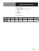
Equipment Description FIRING RATE, BTU/HR MODEL Ignition Natural Propane Gas Gas 40GS-KLS Spark 115,000 115,000 Blodgett 40GS-KLS steam kettles are stainless steel, floor mounted kettles with a selfcontained steam source heated by gas. A closed steam jacket covers the lower 2/3 of the kettle. Heat from the gas burner boils water in the jacket to produce steam under pressure. To ignite the burners, the kettle uses electronic spark ignition. The kettles are stationary (non-tilting).
Equipment Description For kettles, options include: 1. Larger (3 inch) draw-off * 2. Solid disc strainer or strainer with 1/8 inch perforations 3. Water Fill faucet 4. Basket 5. Kettle brush kit 6. Gallon etch marks* 7. Flanged feet * Factory installed options Model Kettle Capacity Jacket Capacity Kettle Inside Diameter Kettle Depth Overall Width Front-to-Back Rim Height 40GS-KLS 40 Gallons 150 liters 7 Gallons 26.
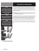
Inspection & Unpacking WARNING THIS UNIT MUST BE INSTALLED BY PERSONNEL WHO ARE QUALIFIED TO WORK WITH ELECTRICITY AND PLUMBING. IMPROPER INSTALLATION CAN CAUSE INJURY TO PERSONNEL AND/OR DAMAGE TO THE EQUIPMENT. THE UNIT MUST BE INSTALLED IN ACCORDANCE WITH APPLICABLE CODES. CAUTION SHIPPING STRAPS ARE UNDER TENSION AND CAN SNAP BACK WHEN CUT. TAKE CARE TO AVOID PERSONAL INJURY OR DAMAGE TO THE UNIT BY STAPLES LEFT IN THE WALLS OF THE CARTON. CAUTION UNIT WEIGHS FROM 468 LBS (212 KG) TO 1120 LBS (508 KG).
Installation WARNING THIS UNIT MUST BE INSTALLED BY PERSONNEL WHO ARE QUALIFIED TO WORK WITH ELECTRICITY AND PLUMBING. IMPROPER INSTALLATION CAN CAUSE INJURY TO PERSONNEL AND/OR DAMAGE TO THE EQUIPMENT. THE UNIT MUST BE INSTALLED IN ACCORDANCE WITH APPLICABLE CODES. The unit should be installed in a ventilated room for efficient performance. items which may obstruct or restrict the flow of air for combustion and ventilation must be removed.
Installation 10. The internal gas lines of the unit were cleaned and closed off with a gas cock before the unit was shipped from the factory. Free all external gas lines of lint, dirt, metal chips, sealant, grease, oil, and other contaminants, before you connect the lines to the kettle. 11. Connect the gas cock of the kettle to the gas service main with 3/4 inch IPS line or approved equivalent 12.
Initial Start-Up Now that the kettle has been installed, you should test it to ensure that it is operating correctly. 1. Remove literature and packing materials from inside and outside of the unit. 2. Install the TDO valve handle. 3. Put a small amount of water into the kettle. 4. Verify that kettle water level is normal and that kettle is holding vacuum in jacket. Correct if not. (See operating instructions to correct) 5. Make sure the supplies of gas and electric power are on. 6.
Operation WARNING ANY POTENTIAL USER OF THE EQUIPMENT MUST BE TRAINED IN SAFE AND CORRECT OPERATING PROCEDURES. Controls Operator controls for the kettle are: 1. Manual gas valve which controls the supply of gas from the main line to the unit. WARNING KEEP AREA AROUND KETTLE FREE AND CLEAR OF ALL COMBUSTIBLE MATERIALS. DO NOT ATTEMPT TO LIGHT ANY BURNER WITH A FLAME. 2. On-Off (toggle) switch. This switch turns the control circuit power supply on or off. 3.
Operation CAUTION DO NOT OVERFILL THE KETTLE WHEN COOKING, HOLDING OR CLEANING. KEEP LIQUIDS A MINIMUM OF 2-3” (5-8 cm) BELOW THE RIM TO ALLOW FOR STIRRING, BOILING AND SAFE PRODUCT TRANSFER. Power On Indicator Light Heat Indicator Light Low Water Indicator Light Thermostat ON/OFF Toggle Switch C. 2. To Stop Kettle Heating a. Turn the thermostat dial to OFF. b. Turn the toggle switch OFF. c. For a prolonged shut-down: 1. Follow the procedure above. 2.
Sequence of Operation The following “action-reaction” outline is provided to help understand how the kettle works. 1. When the power switch is turned on, it starts the spark igniter and opens the automatic valve for the pilot burner. The spark ignites a pilot flame, which heats the sensor. The sensor then sends a signal to turn off the spark. The flame thereafter acts as a standing pilot until the power is turned off. 2.
Maintenance WARNING WHEN USING THE EQUIPMENT OR TESTING, AVOID ANY EXPOSURE TO THE STEAM BLOWING OUT OF THE SAFETY VALVE. SEVERE BURNS CAN RESULT ON EXPOSED SKIN. FAILURE TO CHECK SAFETY VALVE OPERATION PERIODICALLY COULD RESULT IN PERSONAL INJURY AND/OR DAMAGE TO EQUIPMENT. NOTICE: Contact an authorized representative when repairs are required. A Maintenance & Service Log is provided at the back of this manual.
Maintenance WARNING TO AVOID INJURY, READ AND FOLLOW ALL PRECAUTIONS STATED ON THE LABEL OF THE WATER TREATMENT COMPOUND. C. Jacket Filling Every day, before you turn on the unit, make sure the water level is approximately in the center of the water gauge glass. The jacket was filled at the factory with the proper amount of treated water, and is air-tight, but over time steam may be vented and water lost.
Maintenance E. Component Replacement When component replacement involves breaking a gas pipe connection, check the new connection with soap solution or an appropriate leak detector. DO NOT USE A FLAME TO TEST FOR LEAKS. Internal wiring is marked as shown on the circuit schematic drawings (inside control housing and in this manual). Be sure that new components are wired in the same manner as old components. An examination of the circuit schematic shows that the safety components are wired in series.
Cleaning WARNING KEEP WATER AND SOLUTIONS OUT OF CONTROLS AND BURNERS. NEVER SPRAY OR HOSE THE CONTROL CONSOLE, ELECTRICAL CONNECTIONS, ETC. CAUTION NEVER LEAVE A SANITIZER IN CONTACT WITH STAINLESS STEEL SURFACES LONGER THAN 30 MINUTES. LONGER CONTACT CAN CAUSE CORROSION. CAUTION DO NOT MIX PARTS OF DIFFERENT DRAW-OFF VALVE ASSEMBLIES. THE PARTS ARE NOT INTERCHANGEABLE. CAUTION MOST CLEANERS ARE HARMFUL TO THE SKIN, EYES, MUCOUS MEMBRANES AND CLOTHING.
Cleaning NOTICE NEVER LEAVE A SANITIZER IN CONTACT WITH STAINLESS STEEL SURFACES LONGER THAN 30 MINUTES. LONGER CONTACT CAN CAUSE CORROSION. 10. The outside of the unit may be polished with a recognized stainless steel cleaner like “Zepper” from Zep Manufacturing Company. 11. When the equipment needs to be sanitized, use a sanitizing solution equivalent to one that supplies 200 parts per million chlorine. Obtain advice on the best sanitizing agent from your supplier of sanitizing products. 12.
Troubleshooting Your kettle will operate smoothly and efficiently if properly maintained. However, the following is a list of checks to make in the event of a problem. If the actions suggested do not solve the problem, call your qualified Service Representative. If an item on the list is followed by a X , the work should be done by a qualified service representative.
Troubleshooting SYMPTOM WHO WHAT TO CHECK X indicates items which must be performed by an authorized technician. Spark is present but the pilot will not light. Auth Service Rep Only a. That the pilot valve is securely connected to terminals. X b. For 24 VAC at terminals PV and PV/MV. If 24V is not present, replace the ignition control module. X b. That gas pressure is at least 3.5” W.C.(8.7818 b). c. For gas at the pilot. If it is not flowing: (1) Check the pilot gas line for kinks and obstructions.
Parts List Key Description Part # A HARDWARE SPARK IGNITION NAMEPLATE CLASS II 1” X 4-1/2” LONG PLATE, CAUTION 1-3/8 X 2-1/4” CHAIN SINGLE, JACK LINK #16 600” LONG 139192 SCREW, SHEET METAL PAN HD #12 X 1/2” LG B C D BRACKET, FAUCET MOUNTING 16 GA X 4-3/4” NUT HEX KEPS 1/4”-20 W/ SHAKEPROOF WASHER NAMEPLATE, LARGE LABEL, WARRANTIES VOID LABEL WARNING COVER POWER AID ASSEMBLY POT INNER ASSEMBLY TDO KIT NUT, WING #10-24 FOR 1-1/2” & 2” HANDLE, 3” DIA SANITARY & TDO VALVE STRAINER ASSEMBLY 9” DIA, 1/4
Parts List Key F 1 1 2 3 3 4 5 6 7 Description BURNER AND SENSOR ASSEMBLY (NATURAL GAS) BURNER AND SENSOR ASSEMBLY (PROPANE) ASM.BURNER MANIFOLD (NATURAL GAS) ASM. BURNER MANIFOLD (PROPANE) PILOT BRACKET ASM. PILOT BURNER (NATURAL GAS) ASM.
Parts List 22 OM-40GS-KLS
Parts List OM-40GS-KLS 23
Parts List Key Description Part No. Key Description ELECTRICAL MOUNTING ASSEMBLY Part No. G GAS VALVE, PIPING ASSY 139197 139060 3 WATER LEVEL ELECTRODE 074665 1 ASM., ELECTRICAL PANEL 139187 4 ELECTRICAL COMPONENTS ASSEMBLY 139060 2 WATER LEVEL CONTROL BOARD 122192 5 IGNITION MODULE BOX ASSEMBLY 127334 3 PC BOARD MOUNTING POST 099901 6 ELBOW, 90º UNION, 1/2” NPT 005495 4 FUSE BLOCK 077854 7 NIPPLE, 1/2” NPT X 8” LONG 005557 5 FUSE 3.
Electrical Schematic OM-40GS-KLS 25
Service Log Model No: Purchased From: Serial No: Location: Date Purchased: Date Installed: Purchase Order No: For Service Call: Date 26 OM-40GS-KLS Service Performed Performed By
Service Log Model No: Purchased From: Serial No: Location: Date Purchased: Date Installed: Purchase Order No: For Service Call: Date Service Performed Performed By OM-40GS-KLS 27
28 OM-40GS-KLS
OM-40GS-KLS 29
BLODGETT OVEN COMPANY www.blodgett.