Blizzard Lighting, LLC www.blizzardlighting.
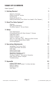
TABLE OF CONTENTS Solar System™ 1 1. Getting Started 3 What’s In The Box? Getting It Out Of The Box Powering Up! Getting A Hold Of Us Safety Instructions (Don’t Stick Your Hand In The Toaster!) 3 3 3 3 4 2. Meet The Solar System™ 5 Features DMX Quick Reference The Solar System™ Pin-up Picture 5 5 6 3.
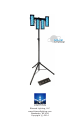
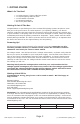
1. GETTING STARTED What’s In The Box? • • • • • 1 x Solar System™ Fixture LED Bar w/Case 1 x Tripod Lighting Stand w/Case 1 x Foot Switch Controller 2 x Mounting Brackets This Lovely User Manual Getting It Out Of The Box Congratulations on purchasing one of the coolest LED lighting systems anywhere! Now that you’re the proud owner of a Solar System™ (or hopefully, MORE!), you should carefully unpack the box and check the contents to ensure that all parts are present and in good condition.
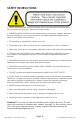
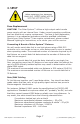
SAFETY INSTRUCTIONS • Please keep this User Guide for future use. If you sell the unit to someone else, be sure that they also receive this User Guide. • ALWAYS make sure that you are connecting to the proper voltage, and that the line voltage you are connecting to is not higher than that stated on the decal or rear panel of the fixture. • This product is intended for indoor use only. • To prevent risk of fire or shock, do not expose fixture to rain or moisture.
2.
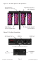
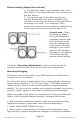
Figure 1: The Solar System™ Pin-Up Picture Rugged Black Aluminum Casings Adjustable Position LED Fixtures High Power 10mm R/G/B LEDs Adjustable Height Tripod Stand Figure 2: The Rear Connections AC Power Out DMX In DMX Out 4-Button LED Control Panel Footswitch Input AC Power In Page 6 Solar System™ User Manual Rev.
3. SETUP Fuse Replacement CAUTION! The Solar System™ utilizes a high-output switch-mode power supply with an internal fuse. Under normal operating conditions, the fuse should not require replacement. The fuse is field replaceable, however it is an advanced procedure suited to qualified individuals. Should your Solar System™ fuse require replacement, please contact Blizzard Lighting for instructions, or to return your unit for service.
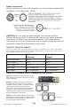
Cable Connectors Cables must have a male XLR connector on one end and a female XLR connector on the other end. (Duh!) CAUTION: Do not allow contact between the common and the fixture’s chassis ground. Grounding the common can cause a ground loop, and your fixture may perform erratically. Test cables with an ohm meter to verify correct polarity and to make sure the pins are not grounded or shorted to the shield or each other.
Fixture Linking (Master/Slave Mode) 1. Connect the (male) 3 pin connector side of the DMX cable to the output (female) 3 pin connector of the first fixture. 2. Connect the end of the cable coming from the first fixture which will have a (female) 3 pin connector to the input connector of the next fixture consisting of a (male) 3 pin connector. Then, proceed to connect from the output as stated above to the input of the following fixture and so on.
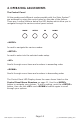
4. OPERATING ADJUSTMENTS The Control Panel All the goodies and different modes possible with the Solar System™ are accessed by using the control panel on the side of the fixture. There are 4 control buttons below the LED display which allow you to navigate through the various control panel menus. MODE SETUP UP DOWN Is used to navigate the various modes. Is used to enter into the selected mode setup. Scrolls through menu items and numbers in ascending order.
Control Panel Menu Structure d001 d001 - d512 To choose the DMX address 3-CH To choose 3 channel DMX mode 5-CH To choose 5 channel DMX mode 48CH To choose 48 channel DMX mode Pr-- Pr01 - Pr18 Built-in programs SP01 - SPFL Speed adjustment (slow <--> fast) FS 00 - F599 Strobe speed (slow <--> fast) n001 - n100 Auto mode SP01 - SPFL Speed adjustment (slow <--> fast) FS 01 - F599 Strobe speed (slow <--> fast) AU7O SLAu Sets the fixture to run in slave mode SU--
DMX Mode Allows the unit to be controlled by any universal DMX controller. 1.) The default mode for the fixture is DMX, which appears as d001 on the LED readout. To select a different DMX address, hit the button and use the buttons to select the your desired starting DMX address, then hit again to confirm your choice. Auto, Master/Slave, Sound Active Modes: Allows a single or Master/Slaved units to run factory installed programs at user selectable speeds. 1.
The Solar System™ Foot Switch Controller Pedal 1 - Auto Run When you step on pedal 1 on the foot controller, it will set your fixtures to run in auto mode. The auto mode program settings are adjustable from the LED control panel menu. Pedal 2 - Sound Active When you step on pedal 2 on the foot controller, it will set your fixtures to run in sound active mode. The built-in microphone sensitivity settings are adjustable from the LED control panel menu.
DMX Values In-Depth (48-Channel Mode) Channel Value What It Does 1 000 <--> 255 Fixture 1, Section 1, Red Intensity (0% <--> 100%) 2 000 <--> 255 Fixture 1, Section 1, Green Intensity (0% <--> 100%) 3 000 <--> 255 Fixture 1, Section 1, Blue Intensity (0% <--> 100%) 4 000 <--> 255 Fixture 1, Section 2, Red Intensity (0% <--> 100%) 5 000 <--> 255 Fixture 1, Section 2, Green Intensity (0% <--> 100%) 6 000 <--> 255 Fixture 1, Section 2, Blue Intensity (0% <--> 100%) 7 000 <--> 255 Fixture
DMX Values In-Depth (48-Channel Mode, continued) Channel Value What It Does 37 000 <--> 255 Fixture 4, Section 1, Red Intensity (0% <--> 100%) 38 000 <--> 255 Fixture 4, Section 1, Green Intensity (0% <--> 100%) 39 000 <--> 255 Fixture 4, Section 1, Blue Intensity (0% <--> 100%) 40 000 <--> 255 Fixture 4, Section 2, Red Intensity (0% <--> 100%) 41 000 <--> 255 Fixture 4, Section 2, Green Intensity (0% <--> 100%) 42 000 <--> 255 Fixture 4, Section 2, Blue Intensity (0% <--> 100%) 43 000
5. APPENDIX A Quick Lesson On DMX DMX covers (and is an abbreviation for) Digital MultipleXed signals. It is the most common communications standard used by lighting and related stage equipment. DMX provides up to 512 control “channels” per data link. Each of these channels was originally intended to control lamp dimmer levels. You can think of it as 512 faders on a lighting console, connected to 512 light bulbs.
Keeping Your Solar System™ As Good As New The fixture you’ve received is a rugged, tough piece of pro lighting equipment, and as long as you take care of it, it will take care of you. That said, like anything, you’ll need to take care of it if you want it to operate as designed. You should absolutely keep the fixture clean, especially if you are using it in an environment with a lot of dust, fog, haze, wild animals, wild teenagers or spilled drinks.
Tech Specs! Weight & Dimensions Width Main Unit: 22.9”(580 mm), Foot Controller: 17 inches (432 mm), Power Cord: 16 ft Length Depth Main Unit: 6.5”(165 mm), Foot Controller: 6 inches (152.4 mm) Height Main Unit: 11.62 inches (295 mm), Foot Controller: 2⅛ inches (5.5 cm) Weight Main Unit: 10.15 lbs (4.6 kg), Foot Controller: 3.5 lbs (1.6 kg), Stand: 8 lbs (3.63 kg) Power Operating Voltage AC 100-240VAC, 50/60 Hertz Power Consumption 42W, .47A Fuse 125V 1A Power Factor .
This page intentionally left blank. Page 19 Solar System™ User Manual Rev.
Enjoy your product! Our sincerest thanks for your purchase! --The team @ Blizzard Lighting