
User Manual


Page 9
ROCKER PANEL RGBAW Manual Rev. A Copyright (c) 2010 Blizzard Lighting, LLC
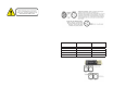
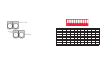
Fixture Linking (Master/Slave Mode)
1. Connect the (male) 3 pin connector side of the
DMX cable to the output (female) 3 pin connector of
the fi rst fi xture.
2. Connect the end of the cable coming from the
fi rst fi xture which will have a (female) 3 pin connec-
tor to the input connector of the next fi xture con-
sisting of a (male) 3 pin connector. Then, proceed
to connect from the output as stated above to the
input of the following fi xture and so on.
A quick note: Often,
the setup for Master-
Slave and Standalone
operation requires that
the fi rst fi xture in the
chain be initialized for
this purpose via either
settings in the control
panel or DIP-switches.
Secondarily, the fi xtures
that follow may also re-
quire a slave setting.
Check the “Operating Adjustments” section in this manual for com-
plete instructions for this type of setup and confi guration.
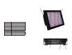
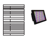
Mounting & Rigging
This fi xture may be mounted in any SAFE position provided there is
enough room for ventilation.
It is important never to obstruct the fan or vents pathway. Mount the
fi xture using a suitable “C” or “O” type clamp. The clamp should be
rated to hold at least 10x the fi xture’s weight to ensure structural sta-
bility. Do not mount to surfaces with unknown strength, and ensure
properly “rated” rigging is used when mounting fi xutres overhead.
Adjust the angle of the fi xture by loosening both knobs and tilting the
fi xture. After fi nding the desired position, retighten both knobs.
• When selecting installation location, take into consideration lamp
replacement access (if applicable) and routine maintenance.
• Safety cables MUST ALWAYS be used.
• Never mount in places where the fi xture will be exposed to rain,
high humidity, extreme temperature changes or restricted ventilation.
Page 10
ROCKER PANEL RGBAW Manual Rev. A Copyright (c) 2010 Blizzard Lighting,
LLC
4. OPERATING ADJUSTMENTS
The Dip Switches
All of the various functions of the ROCKER PANEL™ RGBAW are set up using
the 10-position DIP switch located on the rear of the unit. Using this set of
switches, you can select several different standalone, master/slave and DMX
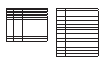
operating modes. The chart below describes the various operating modes and
their respective DIP switch settings.
Function DIP 1 DIP 2 DIP 3 DIP 4 DIP 5 DIP 6 DIP 7 DIP 8 DIP 9 DIP 10
All Red ON
All Green ON
All Blue ON
All Amber ON
All White ON
Strobes Slow Fast
Auto Chase Slow Med. Fast Hyper ON OFF
Sound Active OFF OFF OFF OFF OFF OFF OFF OFF ON OFF
Slave ON OFF OFF OFF OFF OFF OFF OFF OFF ON
DMX CH. # 1 2 4 8 16 32 64 128 256 ON
The Control Panel LED Display shows the menu items you select from
the menu map on page #11. When a menu function is selected, the
display will show immediately the fi rst available option for the selected
menu function. To select a menu item, press <ENTER>.
Press the <MENU> button repeatedly until you reach the desired
menu function. Use the <UP> and <DOWN> buttons to navigate the
menu options. Press the <SAVE> button to select the menu function
currently displayed, or to enable a menu option. To return to the previ-
ous option or menu without changing the value, press the
<MENU> button.