
User Manual


Page 7
COLORStorm 252 Manual Rev. B Copyright (c) 2010 Blizzard Lighting, LLC
Cable Connectors
Cables must have a male XLR connector on one end and a female XLR
connector on the other end. (Duh!)
CAUTION: Do not allow contact between the common and the fi x-
ture’s chassis ground. Grounding the common can cause a ground
loop, and your fi xture may perform erratically. Test cables with an
ohm meter to verify correct polarity and to make sure the pins are not
grounded or shorted to the shield or each other.
3-Pin??? 5-Pin??? Huh?!?
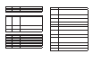
If you use a controller with a 5 pin DMX output connector, you will need to use a 5 pin to 3 pin adapter.
They are widely available over the internet and from specialty retailers If you’d like to build your own, the
chart below details a proper cable conversion:
Conductor 3-Pin Female
(Output)
5-Pin Male
(Input)
Ground/Shield Pin 1 Pin 1
DMX Data (-) Pin 2 Pin 2
DMX Data (+) Pin 3 Pin 3
Not Used. No Connection. No Connection.
Not Used. No Connection. No Connection.
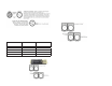
Take It To The Next Level: Setting Up DMX Control
Step 1: Connect the male connector of the
DMX cable to the female connector (output)
on the controller.
Step 2: Connect the female connector of the
DMX cable to the fi rst fi xture’s male connec-
tor (input). Note: It doesn’t matter which
fi xture address is the fi rst one connected.
We recommend connecting the fi xtures in
terms of their proximity to the controller,
rather than connecting the lowest fi xture
number fi rst, and so on.
Step 3: Connect other fi xtures in the chain
from output to input as above. Place a DMX
terminator on the output of the fi nal fi xture
to ensure best communication.
Page 8
COLORStorm 252 Manual Rev. B Copyright (c) 2010 Blizzard Lighting, LLC
Fixture Linking (Master/Slave Mode)
1. Connect the (male) 3 pin connector side of the
DMX cable to the output (female) 3 pin connector of
the fi rst fi xture.
2. Connect the end of the cable coming from the
fi rst fi xture which will have a (female) 3 pin connec-
tor to the input connector of the next fi xture con-
sisting of a (male) 3 pin connector. Then, proceed
to connect from the output as stated above to the
input of the following fi xture and so on.
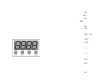
A quick note: Often,
the setup for Master-
Slave and Standalone
operation requires that
the fi rst fi xture in the
chain be initialized for
this purpose via either
settings in the control
panel or DIP-switches.
Secondarily, the fi xtures
that follow may also re-
quire a slave setting.
Check the “Operating Adjustments” section in this manual for com-
plete instructions for this type of setup and confi gur ation.
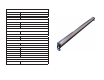
Mounting & Rigging
This fi xture may be mounted in any SAFE position provided there is
enough room for ventilation.
It is important never to obstruct the fan or vents pathway. Mount the
fi xture using a suitable “C” or “O” type clamp. The clamp should be
rated to hold at least 10x the fi xture’s weight to ensure structural sta-
bility. Do not mount to surfaces with unknown strength, and ensure
properly “rated” rigging is used when mounting fi xutres overhead.
Adjust the angle of the fi xture by loosening both knobs and tilting the
fi xture. After fi nding the desired position, retighten both knobs.
• When selecting installation location, take into consideration lamp
replacement access (if applicable) and routine maintenance.
• Safety cables MUST ALWAYS be used.
• Never mount in places where the fi xture will be exposed to rain,
high humidity, extreme temperature changes or restricted ventilation.