
Installation guide
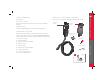


HIGH POWER WALL CONNECTOR
10
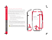
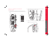
STEP FOUR - MOUNT CONNECTOR
1. Position the connector over the bolts on the mounting bracket as
shown below.
2. Attach the grounding wire as shown above.
3. Fasten the connector onto the bracket using the supplied flange
screws. Use a ratchet wrench and 8 mm socket to tighten until snugly
fitted.
Mounting Bracket
attached to wall
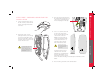
STEP FIVE - CONNECT WIRING
NOTE: For most branch circuits of 100A, use 3 AWG (26.7 mm
2
), 75°C
(167°F) copper wire. For installations less than 100A, use conductors that
are sized according to local electrical codes.
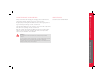
WARNING: Do not connect service wiring until you have read and fully understand
the pages in this document titled “Service Wiring.” If you are uncertain about the type
of power available at the service panel, consult your local utility, or contact Tesla for
assistance.
1. Turn off the power.
WARNING: RISK OF ELECTRIC SHOCK! Before connecting the wiring, use a volt
meter to confirm that NO POWER is available at the service wiring or terminals.
2. Pull the service wiring into the High Power Wall Connector. If using a
hub, connect conduit to the hub before connecting it to the enclosure.
3. Strip wires ⅜ ” (10 mm).
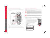
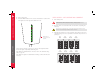
4. Connect wiring to the terminal block. Connect
L1 to Black, L2/N to Red, and Ground to one of
the two available Ground connectors, as shown.
NOTE: Maximum size of Ground wire is4AWG.
5. Tighten L1 and L2 screws to 35-50 lb-in,
depending on wire gauge. Tighten Ground
screw as follows:
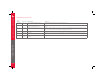
Wire Gauge
AWG CU-AL Torque (lb-in)
14~10 CU
12-10 Al
20
825
6~4 35
Two 14 or 12 CU
Two 12 or 10 Al
25
INSTALLATION
L1 L2/N
use either of these
connections to
attach GND