
Operating instructions


Page 4
SECTION 2: COMPONENT OVERVIEW
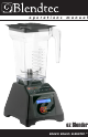
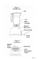
2.1 BLENDER MOTOR
The blender motor consists of the blender base, touch pad control, and
Liquid Crystal Display (LCD) information center. (See Figures 1 and 2.)
● Motor housing: Houses the power unit in a plastic casing. Never
remove the motor cover. Removal of the motor cover will void the
warranty.
● Touch Pad: Consists of six buttons which contain pre-programmed
settings as well as a pulse for selective blender control.
● LCD Information Center: When a cycle is completed, the display
increments the cumulative cycle for warranty purposes. It also indicates
overload or over-temperature conditions.
● Blender Motor: This unit is located within the motor housing and
contains the machinery which runs the blender, including the electric
motor, drive train, and computerized control board.
2.2 BLENDER JAR ASSEMBLY
The blender jar assembly consists of the blender jar, blade assembly,
and lid. The blender jar assembly integrates these components to
ensure consistently blended drinks and greater operator safety.
● Jar: Made from polycarbonate to provide maximum performance as
well as clear visibility of blender performance.
● Blade Assembly: Stainless steel, designed to ensure fast, consistent
blending.
● Lid: Designed to provide ease of handling and quick removal for high
speed operations.
2.5 POWER SPECIFICATIONS
The ez Blender is certied for use on 110/120 volt circuits and is limited
to 13 amps. It is required that this unit be installed with a 15 amp
protected circuit. Recommended protection for this unit is a 20 amp
dedicated circuit.