
Owner's Manual

PART# BRX-2021
Blend
fflount-
®
EradEDSO:
11
11
1
1111
11
111
1
11
11
111
1111
11
11
Innovative
Mounting
Solutions
LEFT
HAND
DRIVE VEHICLE
7
28028
44286
1
INSTALLATION INSTRUCTIONS
FOR
RADENSO
XP
RADAR DETECTOR
Your
rear
view
mirror
has mlnlmal clearance between
the
back
aide
of
the
mirror
and
the
mirror
stem.
It
la
very
Important
that
this
mount
la Installed correctly to ensure
mirror
adJuatablllty
Is
retained.
PLEASE
READ
THESE INSTRUCTIONS THOROUGHLY BEFORE INSTALLING THIS MOUNT
NOTE:
For
lllu.tratlon
purpONS,
the
mount
and
rear
view
mirror
shown
In
these
Instructions
may
look
sllghtly
dlffel'llllt
then
YOUR
mount
and
rear
view
mirror.
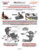
B&for8
lnstalllng
this
mount
on
your
mirror
observe
how
the
spring clip functions.
When
used
property,
the
spring
cllp
avoids
putting
axceulva
prvuure
on
the
mirror
when
lnstalllng
and
removing
the
radar
detector
(RD).
To
releaae tension
from
the
spring cllp, simply squeeze
the tab
and
tt,e back aide
af
tt,e mount togett1er. Thia wlll lower tt,e bottom portion
af
the
spring clip allowing you
to
allele
the
RD
on
and
off
the
mount. Push tt,e
RD
Release button and slide
the
RD
onto
tt,e Spring
Clip
until you
hear
it
lock into position, then release both tt,e Tab and Release Button. Install and
remove tt,e
RD
a few
times
before installing
the
mount
on
your
mirror.
Once
the
Installation
la
comp..._,
the
spring
cllp
allows
you
to
access
the
buttons
on
top
of
the
RD
wlllle
91111
having
the
RD
Installed
to
an
u
close
to
the
bottom
of
the
rear-view
mirror
u
poulble.
By
gently pushing
down
on
the
RD
the
spring clip
is
designed
to
flex
downward allowing you ID push desired buttons,
then
it
will
spring back into its original position
when
you
take
your
finger away. This can al&0
be
uaefull
11::1
a0C8118
the releaae button.
s'
~Q
BODY
ASSEMBLY
MIDSECTION
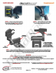
STEP 1 • L0098n
the
clamp
aaew
so
tt,e
top
section separ-
ates from
the
mid section.
This
will provide the necessary clear-
ance
to
slide
the
mount
over
the
mirror stem
as
shown
above.
Adju.t
th
e
mi
rror
paralell
to
the
wlndshleld
and
allghtly
upward
for
ease
of
lnstallatlon.
TOPANDMID
SECTIONS
MUST
TOUCH
AT
THE
PIVOT POINT
BEFORE CLAMP SCREW
IS
FULLY
TIGHTENED
PIVOT
POINT
CLEARANCE
FOR
MIRROR
STEM
PAGE1
OF2
STEP
2 • BEFORE
FULLY
TIGHTENING
lllE
CLAMP
SCREW, POSITION
lllE
MOUNT
AS
FAR
FORWARD
TO-
WARDS
THE
WINDSHIELD
AS
YOU
CAN.
MAKE
SURE
lllE
TOP
AND
MID
SECTIONS
ARE
TOUCHING
AT
THE
PIVOT
POINT.
If
you can
not
get
them
to
touch
at
the
pivot point,
you
have
an
Incompatible
mirror
type
forthla
mount