
Owner's Manual

PART# BRD-3030
Bien
ounf-®
Er
d:
•=
111111111111\~II
Ill
II
I I
I\
II
Innovative
Mounting
Solutions
LEFT HAND DRIVE VEHICLE
'7
2802
4
3667
9
INSTALLATION INSTRUCTIONS FOR RADENSO
RADAR
DETECTORS
Your rear
view
mirror
has
minimal
clearance between
the
back
side
of
the
mirror
and
the
mirror
stem.
It
is
very
im-
portant
that
this
mount
is
installed
correctly
to
ensure
mirror
adjustability
is
retained.
PLEASE READ THESE INSTRUCTIONS THOROUGHLY BEFORE INSTALLING THIS MOUNT
NOTE: For illustration purposes, the mount and rear view mirror shown in these instructions may look slightly different then YOUR
mount and rear view mirror.
Before installing this mount on your mirror observe how the spring clip functions. When used properly, the spring clip avoids putting excessive
pressure
on
the mirror when installing and removing the radar detector (RD).
To
release tension from the spring clip, simply squeeze the tab and
the back side
of
the mount together. This will lower the bottom portion
of
the spring clip allowing you to slide the RD on and off the mount. Push the RD
Release button and slide the RD onto the Spring Clip until you hear it lock into position, then release both the Tab and Release Button. Install and
remove the RD a few times before installing the mount on your mirror. Once the installation is complete, the spring clip allows you to access the
buttons on top
of
the RD while still having the RD installed to sit as close to the bottom
of
the rear-view mirror as possible. By gently pushing
down on the RD the spring clip is designed to flex downward allowing you to push desired buttons, then it will spring back into its original position when
you take your finger away. This can also be useful! to access the release button.
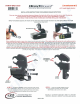
TOP
SECTION
MID
SECTION
STEP 1 • The BODY ASSEMBLY must be removed to gain access
to the CLAMP SCREW. Remove the two socket head screws as shown
above. Be sure to remove the lock washer with the top screw along
with the lock washer and flat washer with the bottom screw.
Innovative Design
And
Precision Manufacturing
PAGE 1 OF 2
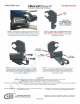
STEP 2 • Loosen the CLAMP SCREW so there
is enough clearance between the TOP and MID
SECTIONS to slide over the mirror stem.
BlendMount - US PATENT#
0625
,580
S,
0656,811
S,
0653
,980 S
0690,245
S,
0690
,246
S,
0690
,247
Sand
other patents pending