
Installation Guide
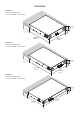
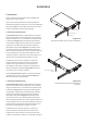
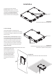
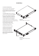

Diagram 3c
2 x PowerZone 504 with connection plate.
Connection Plate +
4 x M3 x 6 csk
Installation
Diagram 4a
PowerZone 252/504 with desk/wall mounting plate and
adhesive feet. 2 positions and 4 positions.
Diagram 4b
PowerZone 252/504 under-desk and wall mounted.
5.3 Free-standing
If not to be installed in an equipment rack,
PowerZone ampliers can be placed free-standing
on a at surface. Adhesive rubber feet are supplied
for this purpose.
PowerZone 504 and PowerZone 252 ampliers
can also be attached to the underside of desks or
wall mounted using connecting plate hardware.
The adhesive rubber feet should also be used in
these circumstances to minimise the possibility
of vibration between the amplier and mounting
surface. Wall and desk mounting is illustrated in
Diagrams 4a and 4b.
It is important in any free standing installation that airow
through the amplier’s side
panel mounted fans and rear
panel ventilation apertures is
not compromised by adjacent
items. At least 80mm of free
space behind the amplier
and 25mm along at least one
side should be retained at all
times.
Mounting Plate +
2 x M3 x 6 csk
Adhesive Foot
to signicant movement. Multiple
PowerZone 504 ampliers can also be
mechanically connected using accessory
connecting plates. Diagrams 3b and
3c illustrate the use of rack mount rear
support hardware and connecting plates.