
Installation Guide

Conguration
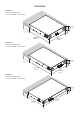
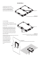
4.2 GPIO Functions
The GPIO connector
is illustrated and its
functions described in
the adjacent matrix.
Note: The GPIO
connector must
not be used for
any unintended
purpose. Amplier
damage may
result from
incorrect use of
GPIO.
Note: In order to
conform to EMC
specications,
shielded cable
must be used
when connecting
external
volume control
potentiometers
via GPIO.
Note: The GPIO GPO connection has an output impedance
of 1kΩ. Connected devices must be able to sink 3.3mA.
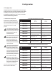
FUNCTION NOTES
GPIO GND (1)
Ground reference for all GPIO
pins
GPIO V12 (2)
Channel 1 & 2 additional gain
control.
Connect to a potentiometer (>10kΩ) wiper
between the VCC and GND pins. Diagram
2a below illustrates these potentiometer
connections. The maximum level available when
using GPIO control is dened by the front panel
gain control setting.
GPIO V34 (3)
Channel 3 & 4 additional
gain control (four channel
ampliers only).
Connect to a potentiometer (>10kΩ) wiper
between the VCC and GND pins. Diagram
2b below illustrates these potentiometer
connections. The maximum level available when
using GPIO control is dened by the front panel
gain control setting.
GPIO VCC (4)
Control voltage output.
Provides a 3.3Vdc control output (100Ω output
impedance) for up to two volume control
potentiometers (>10kΩ).
GPIO STB (5)
Remote standby control.
Pull to GND to engage or disengage standby mode
depending on DIP Switch 7 setting.
GPIO GPO (6)
System status indication.
+3.3Vdc indicates normal status, 0Vdc indicates
one or more channels in protection mode.
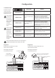
1 2 3 4 5 6
Diagram 2a
Potentiometer connections for remote
volume control via GPIO.
Note: Diagram 7d illustrates
use of the GPIO connector.
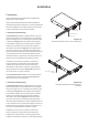
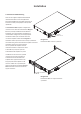
Diagram 2b
Connections for remote standby switch and
status indication via GPIO.
Note: Diagram 7d illustrates
use of the GPIO connector.
8
7
6
5
4
3
2
1
LoZ/HiZ-1
LoZ/HiZ-2
LoZ/HiZ-3
LoZ/HiZ-4
70V/100V
1:All/1:1
Stby No/Nc
Lck/Unlck
GND
VC34
+3V3
Stby
Fault
VC12
INPUT
CH1
CH3
CH2
CH4
Potentiometer
(>10kΩ)
Connect Wiper:
to VC34 for Channel 3 & 4
or VC12 for Channel 1 & 2
Ground
+3V3
8
7
6
5
4
3
2
1
LoZ/HiZ-1
LoZ/HiZ-2
LoZ/HiZ-3
LoZ/HiZ-4
70V/100V
1:All/1:1
Stby No/Nc
Lck/Unlck
GND
VC34
+3V3
Stby
Fault
VC12
INPUT
CH1
CH3
CH2
CH4
+3V3 = operational
0V = fault
Switch open or closed toggles standby
depending on poition of DIP switch 7.
Ground
Fault
Standby