
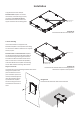
Installation Guide

Conguration
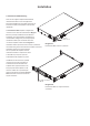
4. Conguration
Amplier operational conguration is set up through
selections made on a rear mounted DIP switch module.
A GPIO (General Purpose In/Out) connector is also
provided that enables access to a variety of amplier
control and monitoring functions.
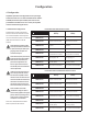
4.1 DIP Switch Conguration
The DIP switch module is illustrated
and its functions described for two and
four channel ampliers in the adjacent
matrices. DIP switch options are selected
(ON) when the switch is in the UP
position.
Note: When input ganging is ON,
each input channel is connected to
its equivalent output. When input
ganging is OFF, all outputs are
connected to input 1.
Note: When the front panel control
lock is ON, the last volume setting
will be frozen and further front
panel volume adjustment will
have no effect. External volume
and standby control via GPIO will
remain operational.
If the front panel volume controls
are turned up while the controls
are locked, the amplier volume
will not increase to match the new
volume level when the controls are
unlocked. To increase the volume,
the controls must rst be turned
down to below their previous level.
Note: An 80Hz second order
(12dB/octave) high-pass lter is
automatically applied to the signal
path of channels operating in Hi-Z
mode in order to prevent speaker
transformer core saturation.
Note: Use a small at blade screwdriver
blade to operate the DIP switches.
OFF
↓
ON
↑
SWITCH 1
Channel 1 in Low-Z mode Channel 1 in Hi-Z mode
SWITCH 2
Channel 2 in Low-Z mode Channel 2 in Hi-Z mode
SWITCH 3
Not Used Not Used
SWITCH 4
Not Used Not Used
SWITCH 5
70V Hi-Z mode
(for channels in Hi-Z mode)
100V Hi-Z mode
(for channels in Hi-Z mode)
SWITCH 6
Input ganging 1: All Input ganging 1:1
SWITCH 7
GPIO standby polarity NO
(Normally Open)
GPIO standby polarity NC
(Normally Closed)
SWITCH 8
Front panel control locked. Front panel control unlocked.
ON
OFF
1 2 3 4 5 6 7 8
OFF
↓
ON
↑
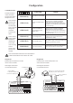
SWITCH 1
Channel 1 in Low-Z mode Channel 1 in Hi-Z mode
SWITCH 2
Channel 2 in Low-Z mode Channel 2 in Hi-Z mode
SWITCH 3
Channel 3 in Low-Z mode Channel 3 in Hi-Z mode
SWITCH 4
Channel 4 in Low-Z mode Channel 4 in Hi-Z mode
SWITCH 5
70V Hi-Z mode
(for channels in Hi-Z mode)
100V Hi-Z mode
(for channels in Hi-Z mode)
SWITCH 6
Input ganging 1: All Input ganging 1:1
SWITCH 7
GPIO standby polarity NO
(Normally Open)
GPIO standby polarity NC
(Normally Closed)
SWITCH 8
Front panel control locked. Front panel control unlocked.
ON
OFF
1 2 3 4 5 6 7 8
PowerZone 252 DIP switch functions
PowerZone 1004 and 504 DIP switch functions