
Installation Guide

Operation
7. Operation
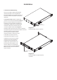
Once all connections have been made and DIP
switches set, the amplier can be connected to
mains power. After a short delay, and if an input
signal above -55dB is present on any input, the
front panel standby indicator will illuminate
green to indicate normal amplier operation.
Note: The ampliers will not switch on from standby mode
unless an input signal is present or the standby switch is toggled.
Set the channel gain controls appropriately in respect of the
input signal level and required speaker volume. Diagrams
8a, 8b and 8c illustrate the front panel controls and
indicators.
Amplier outputs will mute if no input signal is
present for 10 minutes, and the amplier will switch
automatically to standby mode if no signal is present
on any input for more than 25 minutes. Standby mode
can also be triggered remotely via a switch connected
between the STB and GND GPIO connector pins.
Amplier cooling fan speed is temperature controlled. The fan
will switch off when the amplier enters standby mode.
7.1 Standby Indicator
The Standby Indicator changes colour to indicate
operational states:
Green: The amplier is in normal operation mode.
Red: The amplier is in sleep mode following no
input present for more than 10 minutes, or
in standby mode following a GPIO trigger.
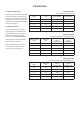
7.2 Signal Indicators
The Signal Indicators adjacent to each channel gain
control knob illuminate in different colours to indicate input
states:
Green: Signal present (> -55dB)
Orange: Output limiter active (0dB)
Red: Input overload, output protection operational or
amplier fault.
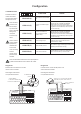
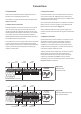
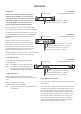
Standby indicator
Gain adjust and signal indicator – Channel 4
Gain adjust and signal indicator – Channel 3
Gain adjust and signal indicator – Channel 2
Gain adjust and signal indicator – Channel 1
Standby indicator
Gain adjust and signal indicator – Channel 4
Gain adjust and signal indicator – Channel 3
Gain adjust and signal indicator – Channel 2
Gain adjust and signal indicator – Channel 1
Diagram 8c
PowerZone 1004 front panel.
Diagram 8b
PowerZone 504 front panel.
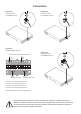
Standby indicator
Gain adjust and signal indicator – Channel 2
Gain adjust and signal indicator – Channel 1
Diagram 8a
PowerZone 252 front panel.
7.3 Automatic Power Sharing
The PowerZone 252 and PowerZone 504 incorporate a power
sharing feature.
PowerZone power sharing automatically shares the total power
available from the amplier’s internal power supply across each
pair of output channels. If one channel temporarily demands
more than the amplier’s continuous power rating while other
channel is demanding less, the excess power available from the
internal power supply is automatically made available to the
over-power channel. Power sharing optimises the amplier’s
ability to deliver maximum power into dynamic loudspeaker
loads when playing music programme material.