
Installation Guide

Hi-Z Connection
+ –
Low-Z Connection
+ –
+ –
Low-Z Connection
+ –
Hi-Z Connection
CH3
CH4
CH1 CH2
5 mm
5 mm
5 mm
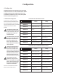
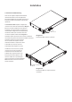
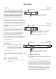
Connections
Diagram 7a
Cable connections
to the input connector.
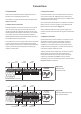
Diagram 7c
Example output connections.
Channel 1: Low-Z connection illustrated
Channel 2: Hi-Z connection illustrated
Channel 3: Hi-Z connection illustrated
Channel 4: Low-Z connection illustrated
Note: DIP switch options must be set appropriately.
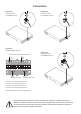
Diagram 7b
Cable connections
to the output connector.
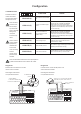
Diagram 7d
Cable connections
to the GPIO connector.
The exclamation point printed next to the output terminals of the ampliers is, in addition to the CLASS 2
WIRING text, intended to alert users to the risk of hazardous voltages. Output connectors that could pose a risk
are marked with the exclamation point. Do not touch the output terminals while the amplier is switched on.
Make all connections with the amplier switched off.