
Installation Guide
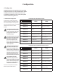
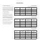

Cable Gauge Table
Low-Z installations. 4Ω & 8Ω loads
Cable Gauge Table
70V Hi-Z installations. 125W & 250W power
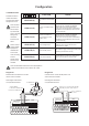
Cable Gauge Table
100V Hi-Z installations. 125W & 250W power
Cable Cross Section
(mm
2
)
Cable Gauge
(US)
Max Cable Length
(metres, 4Ω load)
Max Cable Length
(metres, 8Ω load)
0.5 ≈20 2 5
0.75 ≈18 4 8
1.5 ≈16 6 12
2.0 ≈14 9 19
4.0 ≈12 14 30
Cable Cross Section
(mm
2
)
Cable Gauge
(US)
Max Cable Length
(metres,
(125W/channel)
Max Cable Length
(metres,
(250W/channel)
0.5 ≈20 84 42
0.75 ≈18 132 66
1.5 ≈16 210 105
2.0 ≈14 334 166
4.0 ≈12 532 265
Cable Cross Section
(mm
2
)
Cable Gauge
(US)
Max Cable Length
(metres,
(125W/channel)
Max Cable Length
(metres,
(250W/channel)
0.5 ≈20 171 85
0.75 ≈18 269 134
1.5 ≈16 430 215
2.0 ≈14 683 341
4.0 ≈12 1087 542
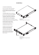
Connections
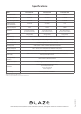
6.4 Speaker Cable Gauge
Speaker connection cable gauge should be
chosen appropriately to reect the type
of installation. The adjacent tables specify
the appropriate cable gauge for less than
0.5dB cable loss with different installation
types and cable lengths.
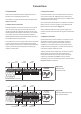
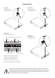
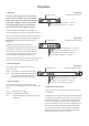
6.5 GPIO Connections
If any GPIO functionality is required,
cables will need to be connected to the
supplied GPIO connector. Connecting
cables to the supplied female GPIO
connector is illustrated in Diagrams 7d.
Note: The maximum recommended GPIO
cable length is 10m (32ft 10in)
Note: The GPIO GPO connection has an
output impedance of 1kΩ. Connected
devices must be able to sink 3.3mA.