
Installation Guide

Connections
6. Connections
Note: The micro USB socket located on amplier rear panels is
present for service and diagnostic purposes only.
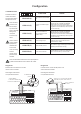
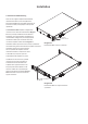
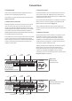
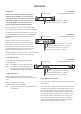
The amplier rear panel connection sockets are illustrated in
Diagrams 6a and 6b.
6.1 Mains Power Connection
PowerZone ampliers incorporate a power factor corrected
universal power supply and can be used with mains input
voltage from 100V AC to 240V AC, 50/60Hz. Use the mains
cable supplied with the amplier and connect it to a switched
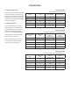
mains supply. The power consumption of the ampliers is
300W, 150W and 75W for the PowerZone 1004, PowerZone
504 and PowerZone 252, respectively.
The ampliers have no mains power switch and are operational
as soon as mains power is connected. Ensure that all signal,
GPIO and output connections are made and that all DIP switch
options are selected appropriately before connecting the
amplier to mains power.
100 - 240 VAC~
50 - 60Hz / 150W
AC MAINS
INPUT
OUTPUT
CLASS 2
WIRING
CLASS 2
WIRING
Input
Channel 1 & 2
Output
Channel 1
GPIO
Input
Channel 3 & 4
Output
Channel 2
Output
Channel 3
Output
Channel 4
CH3
CH4
CH1 CH2
CH1
CH3
CH2
CH4
8
yNo/Nc
Lck/Unlck
GND
VC34
+3V3
Stby
Fault
VC12
Diagram 6b
PowerZone 1004 & PowerZone
504 connection sockets.
8
y No/Nc
Lck/Unlck
GND
VC34
+3V3
Stby
Fault
VC12
100 - 240 VAC~
50 - 60Hz / 150W
BLAZE AUDIO POWERZONE 252 | DESIGNED BY PASCAL IN COPENHAGEN | MANUFACTURED IN CHINA
AC MAINS
INPUT
CH1
CH2
OUTPUT
CLASS 2
WIRING
Input
Channel 1 & 2
Output
Channel 1
GPIO
Output
Channel 2
CH1 CH2
Diagram 6a
PowerZone 252
connection sockets.
6.2 Input Connections
PowerZone amplier inputs are of balanced, line level format
with a input sensitivity of +4dBu (full output voltage swing/
sensitivity) in all modes. Input signal levels up to +24dBu can be
handled without input clipping.
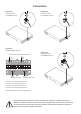
Input connections to the ampliers are achieved via male ‘Euro
Block’ connectors. Connecting cables to the supplied female
input connectors is illustrated in Diagram 7a.
Note: If unbalanced audio sources are used, their negative and
conductor should be connected to both the negative and earth input
terminals.
6.3 Output Connections
Output connections from the ampliers are achieved via male
‘Euro Block’ connectors. Ensure that speaker connection
polarity is correct throughout the installation: positive (+)
amplier terminals should always be connected to positive
speaker terminals and negative (–) amplier terminals always
connected to negative speaker terminals.
Together with DIP switch conguration, the output connector
blocks provide connection options that enable channel
independent selection of Hi-Z or Low-Z mode. Connecting
cables to the supplied female output connector, and the
selection of Hi-Z or Low-Z connection options, are illustrated in
Diagrams 7b and 7c respectively.