INSTALLATION GUIDE / USER MANUAL PowerZone 252 • PowerZone 504 • PowerZone 1004
Technical and Safety Notices Please read the following important technical, safety and environmental notices before installing and using your amplifier. Technical Notices Safety and Environmental Notices All reasonable design and engineering steps have been taken to ensure that these amplifiers always perform satisfactorily in their intended application and environment and will provide appropriate levels of support to ensure that all reasonable customer needs and expectations are met.
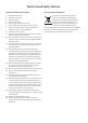
Technical and Safety Notices Important Safety Instructions Environmental Statement 1. 2. 3. 4. 5. 6. 7. This product complies with international directives, including but not limited to the Restriction of Hazardous Substances (RoHS) in electrical and electronic equipment, the Registration, Evaluation, Authorization and restriction of Chemicals (REACH) and the disposal of Waste Electrical and Electronic Equipment (WEEE).
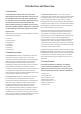
Introduction and Overview 1. Introduction The amplifiers described in this user manual have been designed to provide configurable, consistent and reliable high performance audio power amplification for commercial and entertainment applications. Please read this installation and operation manual fully before installing and using an amplifier. If you have any questions regarding amplifier configuration, installation or operation please contact the appropriate customer support portal.
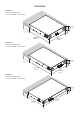
Overview Diagram 1a PowerZone 252 dimensions. Shaded area defines ventilation space. 44 mm 1.7 in 80 mm 3.1 in 25 mm 1 in 260 mm 10.3 in 220 mm 8.7 in Diagram 1b PowerZone 504 dimensions. Shaded area defines ventilation space. 44 mm 1.7 in 80 mm 3.1 in 337 mm 13.3 in 25 mm 1 in 220 mm 8.7 in Diagram 1c PowerZone 1004 dimensions. Shaded area defines ventilation space. 44 mm 1.7 in 25 mm 1 in 80 mm 3.1 in 292 mm 11.5 in 440 mm 17.
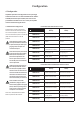
Configuration 4. Configuration Amplifier operational configuration is set up through selections made on a rear mounted DIP switch module. A GPIO (General Purpose In/Out) connector is also provided that enables access to a variety of amplifier control and monitoring functions. 4.1 DIP Switch Configuration The DIP switch module is illustrated and its functions described for two and four channel amplifiers in the adjacent matrices. DIP switch options are selected (ON) when the switch is in the UP position.
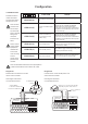
Configuration 4.2 GPIO Functions 1 The GPIO connector is illustrated and its functions described in the adjacent matrix. 2 3 4 5 GPIO GND (1) Note: The GPIO connector must not be used for any unintended purpose. Amplifier damage may result from incorrect use of GPIO. NOTES Ground reference for all GPIO pins Channel 1 & 2 additional gain control. Connect to a potentiometer (>10kΩ) wiper between the VCC and GND pins. Diagram 2a below illustrates these potentiometer connections.
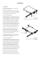
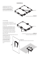
Installation 5. Installation Note: It is important in all installations that the amplifier mains supply switch is easily accessible. Note: The rack mounting and desk/wall mounting components described and illustrated in Sections 5.1 to 5.3 are not supplied with PowerZone amplifiers but are available to purchase as accessories. Contact your amplifier re-seller for more information. Rack Ear + 2 x M4 x 8 csk 5.
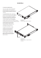
Installation to significant movement. Multiple PowerZone 504 amplifiers can also be mechanically connected using accessory connecting plates. Diagrams 3b and 3c illustrate the use of rack mount rear support hardware and connecting plates. Connection Plate + 4 x M3 x 6 csk Diagram 3c 2 x PowerZone 504 with connection plate. 5.3 Free-standing If not to be installed in an equipment rack, PowerZone amplifiers can be placed free-standing on a flat surface. Adhesive rubber feet are supplied for this purpose.
Installation 5.4 PowerZone 1004 Mounting Note: The rear support components described and illustrated in Sections 5.4 are not supplied with PowerZone amplifiers but are available to purchase as accessories. Contact your amplifier re-seller for more information. The PowerZone 1004 amplifier is shipped with rack mount ‘ears’ attached as illustrated in Diagram 5a and is primarily intended to be installed in an equipment rack.
Connections 6. Connections 6.2 Input Connections Note: The micro USB socket located on amplifier rear panels is present for service and diagnostic purposes only. PowerZone amplifier inputs are of balanced, line level format with a input sensitivity of +4dBu (full output voltage swing/ sensitivity) in all modes. Input signal levels up to +24dBu can be handled without input clipping. The amplifier rear panel connection sockets are illustrated in Diagrams 6a and 6b.
Connections 6.4 Speaker Cable Gauge Speaker connection cable gauge should be chosen appropriately to reflect the type of installation. The adjacent tables specify the appropriate cable gauge for less than 0.5dB cable loss with different installation types and cable lengths. 6.5 GPIO Connections If any GPIO functionality is required, cables will need to be connected to the supplied GPIO connector. Connecting cables to the supplied female GPIO connector is illustrated in Diagrams 7d.
Connections Diagram 7a Diagram 7b Cable connections to the input connector. Cable connections to the output connector. 5 mm 5 mm Diagram 7c Example output connections. Diagram 7d Low-Z Connection Hi-Z Connection +– +– CH1 Cable connections to the GPIO connector.
Operation 7. Operation Once all connections have been made and DIP switches set, the amplifier can be connected to mains power. After a short delay, and if an input signal above -55dB is present on any input, the front panel standby indicator will illuminate green to indicate normal amplifier operation. Diagram 8a Standby indicator PowerZone 252 front panel.
Specifications Model PowerZone 252 PowerZone 504 PowerZone 1004 250 W 500 W 1000 W Output Power @ 4/8Ω 2 x 125 W 4 x 125 W 4 x 250 W Output Power @ 70/100V* 2 x 125 W 4 x 125 W 4 x 250 W Powershare (up to) Across all channels** 1 x 250 W 2 x 250 W N/A Power Consumption 75W 150W 300W 44.5 x 220 x 262 mm (1.75 x 8.66 x 10.31 in) 44.5 x 220 x 337 mm (1.75 x 8.66 x 13.27 in) 44.5 x 440 x 292 mm (1.75 x 17.32 x 11.50 in) 1.9 kg (4.2 lbs) 2.4 kg (5.3 lbs) 3.6 kg (7.