
User Guide

8
7
6
5
4
3
2
1
LoZ/HiZ-1
LoZ/HiZ-2
LoZ/HiZ-3
LoZ/HiZ-4
70V/100V
1:All/1:1
Stby No/Nc
Lck/Unlck
GND
VC34
+3V3
Stby
Fault
VC12
INPUT
CH1
CH3
CH2
CH4
Potentiometer
(>10kΩ)
Connect Wiper:
to VC34 for Channel 3 & 4
or VC12 for Channel 1 & 2
Ground
+3V3
QUICK START GUIDE
POWER AMPLIFIERS
PowerZone 252 • PowerZone 504 • PowerZone 1004
Carton Contents
• Amplier unit • Output connector x 1 or 2
• Mains power cable • Adhesive rubber feet x 4
• Input connector x 1 or 2 • Document pack
• GPIO socket connector • Rack Ears (PowerZone 1004)
Support
• A full user manual that includes information
on installation, mounting accessories and
amplier operation is available online. Go to
www.blaze-audio.com or scan the QR code.
SWITCH OFF
↓
ON
↑
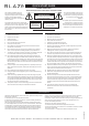
1
Channel 1 in Low-Z mode Channel 1 in Hi-Z mode
2
Channel 2 in Low-Z mode Channel 2 in Hi-Z mode
3
Channel 3 in Low-Z mode* Channel 3 in Hi-Z mode*
4
Channel 4 in Low-Z mode* Channel 4 in Hi-Z mode*
5
70V Hi-Z mode
(for channels in Hi-Z mode)
100V Hi-Z mode
(for channels in Hi-Z mode)
6
Input ganging 1: All Input ganging 1:1
7
GPIO standby polarity NO
(Normally Open)
GPIO standby polarity NC
(Normally Closed)
8
Front panel control
locked.
Front panel control
unlocked.
DIP Switch Functions
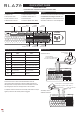
Connections
GPIO Functions
100 - 240 VAC~
50 - 60Hz / 150W
AC MAINS
INPUT
CH1
CH3
CH2
CH4
MAINTENANCE
CH3
CH4
OUTPUT
CLASS 2
WIRING
CLASS 2
WIRING
Input
Channel 1 & 2
Output
Channel 1
GPIO
Input
Channel 3 & 4
Output
Channel 2
DIP
Output
Channel 3
Output
Channel 4
8
7
6
5
4
3
2
1
LoZ/HiZ-1
LoZ/HiZ-2
LoZ/HiZ-3
LoZ/HiZ-4
70V/100V
1:All/1:1
Stby No/Nc
Lck/Unlck
GND
VC34
+3V3
Stby
Fault
VC12
CH1 CH2
• Ensure that rack or other conned installation does not
restrict the airow required for safe and reliable operation of
the equipment. It is important to ensure that the 40°C maximum
operating temperature for the equipment is not exceeded.
• Ampliers will not switch on from standby mode unless an input
signal is present or the standby switch is toggled.
* Not applicable to two channel ampliers.
Installation Notes
• Volume control
• Standby control
and fault indication
8
7
6
5
4
3
2
1
LoZ/HiZ-1
LoZ/HiZ-2
LoZ/HiZ-3
LoZ/HiZ-4
70V/100V
1:All/1:1
Stby No/Nc
Lck/Unlck
GND
VC34
+3V3
Stby
Fault
VC12
INPUT
CH1
CH3
CH2
CH4
+3V3 = operational
0V = fault
Switch open or closed toggles standby
depending on poition of DIP switch 7.
Ground
Fault
Standby