
Service manual


Circuit Descriptions
6-4 Samsung Electronics
1) F/B terminal of PIC1 determines output duty cycle.
2) C-E(Collector-Emitter) of PIC2 and F/B potential of PIC1 are same.
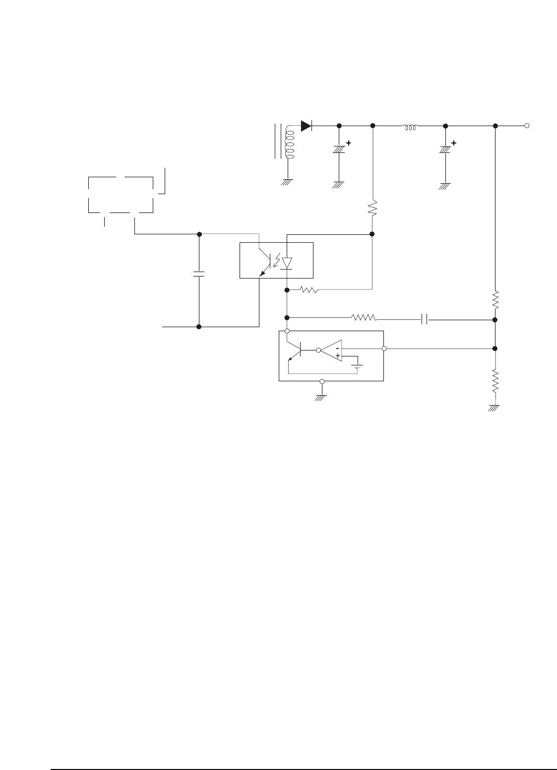
3 Operation descriptions
1) Internal OP-Amp Ô+Õ base potential of PIC3 is 2.5V and external Ò-Ó input potential is connected with PR38 and
PR39 to maintain Vout of 5.8V. (Vout = ((PR36 x PR39) / PR39) x 2.5V)
2) If load of 5.8 V terminal increases(or AC input voltage decreases) and Vout decreases below 5.8V, then :
PIC3 ÔPÕ potential down below 2.5V --> PIC3 A-K of base current down --> PIC3 of A-K current down -->
PIC2 Diode current down --> PIC2 C-E current down --> PIC2 C-E voltage up --> PIC1 F/B voltage up -->
Out Duty up --> Transformer 1st current up --> Transformer 1st power up --> Vout up --> Maintain Vout 5.8V
3) If load of 5.8 V terminal decreases(or AC input voltage rises) and Vout rises above 5.8V, then :
Reverse sequence of the above description --> Duty down --> Vout down --> Maintain 5.8V (i.e., the feedback
to maintains 5.8V).
ΠPR35, PR36 : Reduce 5.8V overshoot
´ PR37, PC44 : Prevent PIC3 oscillation(for phase correction)
ˇ PC09 : Adjust feedback response rate
6-1-2 (d) Feedback Control Circuit
PIC1
STR-G6153T
OCP
DRAIN
F/B
PC09
PIC2
C
E
1st GND
A
K
PIC3
A
2.5V
K
P
PR36
PR37
PC44
2nd GND
PR38
PR39
PR35
PC34
5.8V
PL34
PD33
PE33
Trans
GND
%
! @
#
$
VCC
Fig. 6-8