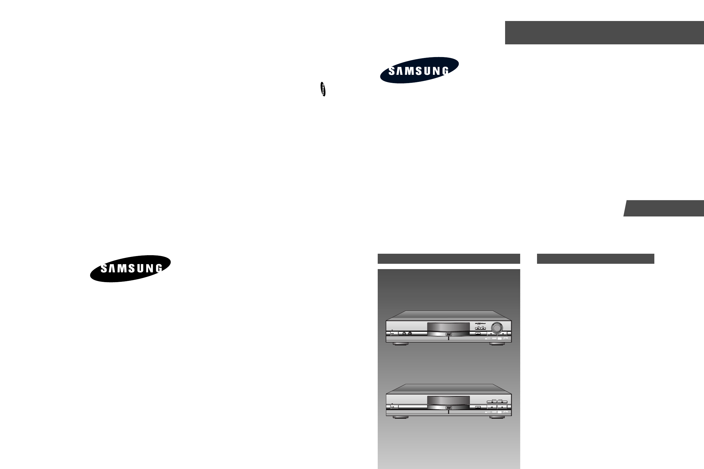
DVD PLAYER DVD-909 DVD-709 SERVICE MANUAL SERVICE Manual DVD-909/709 DVD PLAYER CONTENTS 1. Precautions 2. Reference Information ELECTRONICS 3. Product Specification 4. Operating Instructions 5. Disassembly and Reassembly SKIP STANDBY PHONE DVD/VIDEO-CD/CD PLAYER DVD-909 LEVEL OPEN/ OPEN/ OPEN/ CLOSE CLOSE CLOSE POWER MIN MAX ADVANCED DOLBY DIGITAL DECORDER BUILT-IN SPATIALIZER N-2-2 DIGITAL VIDEO DVD-909 6. Circuit Descriptions 7. Troubleshooting 8. Exploded Views and Parts List 9.
1. Precautions 1-1 Safety Precautions 1) Before returning an instrument to the customer, always make a safety check of the entire instrument, including, but not limited to, the following items: (1) Be sure that no built-in protective devices are defective or have been defeated during servicing. (1)Protective shields are provided to protect both the technician and the customer. Correctly replace all missing protective shields, including any remove for servicing convenience.
Precautions 2) Read and comply with all caution and safety related notes non or inside the cabinet, or on the chassis. 3) Design Alteration Warning-Do not alter of add to the mechanical or electrical design of this instrument. Design alterations and additions, including but not limited to, circuit modifications and the addition of items such as auxiliary audio output connections, might alter the safety characteristics of this instrument and create a hazard to the user.
Precautions 1-2 Servicing Precautions CAUTION : Before servicing Instruments covered by this service manual and its supplements, read and follow the Safety Precautions section of this manual. Note : If unforseen circument create conflict between the following servicing precautions and any of the safety precautions, always follow the safety precautions. Remember: Safety First. 1-2-1 General Servicing Precautions (1) a.
Precautions 1-3 ESD Precautions Electrostatically Sensitive Devices (ESD) Some semiconductor (solid state) devices can be damaged easily by static electricity. Such components commonly are called Electrostatically Sensitive Devices(ESD). Examples of typical ESD devices are integrated circuits and some field-effect transistors and semiconductor chip components. The following techniques should be used to help reduce the incidence of component damage caused by static electricity.
Precautions 1-4 Handling the optical pick-up The laser diode in the optical pick up may suffer electrostatic breakdown because of potential static electricity from clothing and your body. WRIST-STRAP FOR GROUNDING 1M The following method is recommended. (1) Place a conductive sheet on the work bench (The black sheet used for wrapping repair parts.) (2) Place the set on the conductive sheet so that the chassis is grounded to the sheet.
Precautions 1-5 Pick-up disassembly and reassembly 1-5-1 Disassembly 1-5-2 Assembly 1) Remove the power cable. 2) Switch SW3 on deck PCB to ÒOFFÓ before removing the FPC. ( Inserted into Main PCB CN6. See Fig. 1-4) 3) Disassemble the deck. 4) Disassemble the deck PCB. 1) Replace the Pick-up. 2) Assemble the deck PCB. 3) Reassemble the deck. 4) Insert FPC into Main PCB CN6 and switch SW3 on deck PCB to ÒONÓ.
2.
Reference Information 2-1-2 RIC1 (KS1461 ; RF) 83 82 81 80 79 78 77 76 AGC-HOLD(OOH) ADVD 5 AGC_DET RF MUX BCA BLOCK 74 BCAI RF Equalizer RF SLM & AGC C D BCA RFRP GAIN_EQ(02H) CDRSEL(00H) TE1RES DELAY_SEL(OOH) PLLCTL TBAL(O1H) RREFEQ 10 VREF GENERATOR DELAY D GCA RREF 11 CD1 S12 DVD1 DVD2 LDONB FLT_CTL CDRSEL TESEL AGC-HOLD TBAL GAIN_TE3 ENV_SEL DVCTL_SEL DPD_MUTE GAIN_EQ GAIN_FE GAIN_ABCD TE_OFST FE_OFST ABCD_OFST DELAY_CD DELAY_AB PDLIMIT ga_RFSUM HOLD_CTL ga_PLLDP ga_PLLDN HOLD_CT
Samsung Electronics CD optical main beam F input port for SERVO CD optical main beam F input port for SERVO Power voltage input port for analog part CD optical laser monitor diode voltage input port Power GND port for analog part FE AMP output port I I P -/O O I I O I O I P O CCD1 DCD1 AVCC VREFA FOFST OFSTHOLD VREFLP_BGI LDODVD PDDVD LDOCD PDCD AGND FE 21 22 23 24 25 26 27 28 29 30 31 32 33 FEN FOKTH FOKB 45 46 DVCC DVCTTH2 51 52 BCA TE3OFST DPDEQ1 DPDEQ2
2-4 EFMOA EFM ASYCD ASYDVD RFI EFMI DVCTL TBAL FBAL SPD SLD TRD FOD RSTB COUT TILTO FE EFM ASYMETRY D/A CONVERTER BLOCK TRACK COUNTER ROM DSP CORE FOR DIGITAL SERVO PS1 WIDE CAPTURE RANGE PLL SYSCON INTERFACE BLOCK SUB CODE READ BLOCK SSTOP /PSO TE TEST SME XI A/D CONVERTER BLOCK XO TZCO XOUT I/O INTERFACE BLOCK LOCK TIMING GENERATOR SMON ENV VREF PLLHD INTO_224 FDCTL MAGICO EQCTL VCTRL RVCO PLCK EFMRTD RPD PLLLOCK RFD MDOUT[3:0] PSB SENSE MDATA[7:0]
Samsung Electronics Micom data pin 2 Micom data pin 3 Micom data pin 4 Micom data pin 5 Micom data pin 6 Micom data pin 7 Internal status monitor pin Servo logic & ROM VDD power supply pin System clock signal input pin System clock signal output pin Clock out (33.
2-6 FG MON MDP MDS FSW PLL_LOCK CLV_LOCK SERVO_LOCK XTI1 XTO1 CK33MI CK33MO TO (12) EFMI PLCK BCARZ FROM R/F, PLL(3) CD CLV/CAV WFCK 17.58/7.35KHz M SUBCODE I/F 23BIT SR CD-G M SQ-VCD DVDP, MICOM I/F M TEST0, TEST1, TEST2 V-CD, CD-DA DEINTERLEAVE & RAM CONTROL (6, 4, 3) trans ID ECC EDC DESCRAMBLER TO MICOM (15) MDAT(7:0), MRZA, ZCS, MWR, MRD, ZIRQZD, ZWAIT, ZRST Power(34)=VDD(11)+GND(23) Test Pin(3) EFM DEMOD (32, 28, 5) (28, 24, 5) CIRC 75Hz 676.
Samsung Electronics DD5_BI DVSS DD9_BI 31 32 20 DD10_BI DD1_BI 19 30 DD14_BI 18 29 DD0_BI 17 DD4_BI DD15_BI 16 28 DVSS 15 DD11_BI XTO_OUT 14 27 XTI_IN 13 DVDD DVDD 12 DD3_BI MDAT0_BI 11 26 MDAT1_BI 10 25 MDAT2_BI 9 DD12_BI MDAT3_BI 8 24 MDAT4_BI 7 DD2_BI MDAT5_BI 6 23 MDAT6_BI 5 DVSS MDAT7_BI 4 DD13_BI DVSS 3 21 MRZA_IN 2 22 DVSS ZCS_IN 1 NAME PIN DRAM data bus Digital GND (0V) DRAM data bus DRAM data bus DRAM data bus DRAM data bus Di
Reference Information 2-1-5 DIC2 (KM416C254BJ-6 ; CMOS DRAM) BLOCK DIAGRAM RAS UCAS Control LCAS Clocks Vcc VBB Generator Vss W Refresh Timer Row Decoder Lower Data in Buffer Refresh Control Lower DQ0 to DQ7 Data out Memory Array Refresh Counter Buffer 262,144 x 16 Upper Cells Data in Buffer Row Address Buffer AO . . Upper OE DQ8 to DQ15 Data out Col.
Reference Information 2-1-6 VIC1 (ZiVA-3 ; Audio/Video Decoder) BLOCK DIAGRAM ZiVA-3 Decoder OSD Decoder SDRAM/ EDO/ROM Interface Memory Controller Subpicture Decoder Host Interface Host Interface Control Logic MPEG Video Decoder Secure View CD-DA and LPCM Decoder CSS Descrambling Program DVD/CD Interface Stream Decoder Bus Key Dolby Digital Audio Decoder Authentication (Optional) Audio DSP Video Mixer Video Interface Digital Audio Interface Audio Interface Scrambled, Compressed Content
Reference Information 2-1-7 VIC50 (SAA7128 ; Digital Video Encoder) BLOCK DIAGRAM LLC1 VDDA XCLK TTXRQ RCV2 RCV1 XTAL XTALI SCL SDA RESN 25,28,31,36 4 37 8 43 7 34 35 41 42 40 20 VDD I2C 21 I2 C- SYNC/ INTERFACE CLOCK SA Clock&Timing I2 C-Control I2 C-Control 9..
Reference Information PIN I/O 9 I MP7 10 I MP6 11 I MP5 12 I MP4 13 I MP3 14 I MP2 15 I MP1 16 I MP0 17 I V DD2 Digital supply voltage 2 18 I V SS2 Digital ground 2 19 I RTCI 20 I 21 I SA 22 I V SSA1 Analog ground 1 for Red (Cr), C(CVBS), Green(Y) outputs 23 O R(Cr) Analog output of Red (Cr)signal 24 O C 25 I V DDA1 Analog supply voltage 1 for R(Cr), C(CVBS) outputs 26 O G(Y) Analog output of Green(Y) signal 27 O VBS Analog output of VBS (CVBS
Reference Information 2-1-8 MIC1 (TMP93CM41F ; Main Micom) PAO~PA6 PA7(SCOUT) PORT A VCC[3] VSS[3] 900L-CPU P50 to P57 (ANO to AN7) AVCC AVSS VREFH VREFL 10-BIT 8CH A/D CONVERTER XWA XBC ADE XHL XIX XIY XIZ XSP W B D H A C E L (TXD1)P93 (RXD1)P94 (SCLK1)P95 SERIAL I/O OSC IX IY IZ SP 32bit (TXD0)P90 (RXD0)P91 (SCLK0/CTS0)P92 High Frequency SR (CH,0) P C CLK Low F Frequency OSC SERIAL I/O (CH,1) INTERRUPT (PG 00)P60 (PG 01)P61 (PG 02)P62 (PG 03)P63 (PG 10)P64 (PG 11)P65 (PG 12)P66 (PG
Samsung Electronics MC AM8 CLK VCC GND X1 X2 /EA SCLK1 AM8/16 CLK Vcc Vss X1 X2 /EA /RESET 22 23 24 25 26 27 28 29 30 /MRST STB 094 21 RF control data O MD TXD1 20 Serial data clock I SCLK SCLKO Serial data input 19 Serial data output I TXD O RXD TXDO RXDO Interrupt from DSP I ZINT INTO 16 18 45 Request to front micom O RRQ P86 15 17 44 I - INT7 14 Interrupt from spindle motor FG I FGINT /INT6 13 Close switch I CLOSE P83 12 Open sw
Reference Information 2-1-9 MIC8 (M27C801 ; 8MB (1M x 8-bit) CMOS EPROM) BLOCK DIAGRAM Data Outputs DQ0-DQ7 Vcc Vss OE/VPP Output Enable Chip Enable and Prog Logic CE Y Decoder A0-A19 Address Inputs X Decoder Output Buffers Y Gating . . . . . . .
Samsung Electronics TEST1 *RES XT1 11 12 13 VDD AN0/P80 AN1/P81 AN2/P82 AN3/P83 AN4/P84 AN5/P85 AN6/P86 AN7/P87 P70/INT0 P71/INT1 P72/INT2 P73/INT3 18 19 20 21 22 23 24 25 26 27 28 29 30 CF2 P27 17 P26 9 10 CF1 P25 8 16 P24 7 XT2 P23 6 VSS P22 5 15 DIF2 P21 4 14 DIF1 P20 3 REMOCON - - RRQ MODE4 MODE3 MODE2 MODE1 MODE0 - MIC_DET ECHO_VR VDD - - GND - GND - DARST1 DIF0 DARST DEMO1 DEMO0 DFS - MRST P52 PWM1 2 D/A Control
Reference Information MEMO 2-16 Samsung Electronics
3. Product Specifications NTSC GENERAL Power Requirements AC 120V, 60Hz Power Consumption DVD-909 ; 19W, Weight Dimensions Operating Temperature Range Operating Humidity Range DVD (Digital Versatile Disc) CD : 5 inches DISC DVD-709 ; 17W 7.5lbs W 16.9 in X D 11.0 in X H 3.5 in +41°F ~ +95°F 10% to 75% Reading Speed : 11.45 ft/sec. Approx. Play Time (Single Sided, Single Layer Disc) : 135 min. Reading Speed : 3.9 to 4.6 ft/sec. (Compact Disc) Maximum Play Time : 74min.
Product Specification PAL GENERAL Power Requirements AC 110V ~ 240V, 50/60Hz Power Consumption DVD-909 ; 19W, Weight Dimensions W 430mm X D 280mm X H 89mm +5°C ~ 35°C Operating Humidity Range 10% ~ 75% (Digital Versatile Disc) CD : 12cm DISC 3.4Kg Operating Temperature Range DVD (Compact Disc) CD : 8cm (Compact Disc) VCD : 12cm DVD-709 ; 17W Reading Speed : 3.49m/sec. Approx. Play Time (Single Sided, Single Layer Disc) : 135 min. Reading Speed : 1.2 to 1.4m/sec. Maximum Play Time : 74min.
Samsung Electronics PHONE MIN LEVEL MAX ADVANCED DOLBY DIGITAL DECODER BUILT-IN POWER STANDBY OPEN/ OPEN/ OPEN/ CLOSE CLOSE CLOSE DVD-909 DVD/VIDEO-CD/CD PLAYER DVD-909 Description-Front Panel SKIP SPATIALIZER N-2-2 DIGITAL VIDEO DVD/VIDEO-CD/CD PLAYER DVD-709 OPEN/ OPEN/ CLOSE CLOSE SPATIALIZER N-2-2 SKIP DIGITAL VIDEO • When the unit is first plugged in, the indicator lights. When power is pressed on, the lamp goes out.
4-2 L L R L • Connect to the Audio input jacks of your television, audio/video receiver, or VCR. MIXED AUDIO OUT JACKS • Use these jacks if you have a TV with component video in jacks. These jacks provide Pr, Pb and Y video. Along with SVideo, Component Video provides the best picture quality. COMPONENT VIDEO OUT JACKS • Use the S-Video cable to connect this jack to the S-Video jack on your television for a higher quality picture.
A Tour of the Remote Control Samsung Electronics • Use to mark a segment to repeat between A and B. SUBTITLE Button A-B REPEAT Button • Use to access various camera angles on a DVD. ANGLE Button • This button functions as a toggle switch. ENTER/DIRECTION Button (UP/DOWN or LEFT/RIGHT Button) • Brings up the Disc menu. MENU Button • Displays the current disc mode. DISPLAY Button • Allows you to program a specific order. MODE Button • Use to remove menus or status displays from the screen.
4-4 DVD-909 DVD PLAYER TV Better picture Good picture Basic Audio V2 V1 OR OR S-Video Cable (included) S-Video Jack S-VIDEO OUT L2 L1 AV Cable (included) Video Input Jack Method 2 Y Y Best picture COMPONENT VIDEO OUT Pr Pb Pb Pr Component Video Jacks Method 3 Video Cables (not included) • Method 3 DVD Player + TV with Component Video Jacks • Method 2 DVD Player + TV with S-Video Input Jack VIDEO OUT L Method 1 Connecting to a TV (For Video) • Method 1 DVD Player + TV with
DVD-709 Samsung Electronics DVD PLAYER TV S-VIDEO OUT Best picture Basic Audio OR S-Video Cable (included) VIDEO OUT AV Cable (included) Method 2 S-Video Jack Better picture L L Video Input Jack Method 1 • Method 2 DVD Player + TV with S-Video Input Jack • Method 1 DVD Player + TV with Video Input Jack Connecting to a TV (For Video) ANALOG AUDIO OUT R R Audio Input Jacks TV (Normal, Widescreen, Projection, etc..
4-6 PHONE MIN LEVEL MAX ADVANCED DOLBY DIGITAL DECODER BUILT-IN POWER STANDBY DVD/VIDEO-CD/CD PLAYER DVD-909 Description-Front Panel OPEN/ OPEN/ OPEN/ CLOSE CLOSE CLOSE DVD-909 SKIP SPATIALIZER N-2-2 DIGITAL VIDEO DVD/VIDEO-CD/CD PLAYER DVD-709 OPEN/ OPEN/ CLOSE CLOSE SPATIALIZER N-2-2 SKIP DIGITAL VIDEO • When the unit is first plugged in, the indicator lights. When power is pressed on, the lamp goes out.
Samsung Electronics L L R • Use a video cable to connect one of these jacks to the Video input on your television. VIDEO OUT JACKS • Connect to the Audio input jacks of your television, audio/video receiver, or VCR. MIXED AUDIO OUT JACKS • Connect to a video recorder or other equipment. SCART AV2 JACK • Connect to a TV with scart input jack. SCART AV1 JACK • Use a video cable to connect this jack to the Video input on your television.
4-8 FRONT L VIDEO OUT S-VIDEO OUT V2 V1 Pr Y COMPONENT VIDO OUT Pb TV SYSTEM SELECT TV SYSTEM SELECT SWITCH • Use the switch to set TV system. • Connect to an amplifier with 5.1ch analog input jacks. MIXED AUDIO OUT JACKS • Connect to the Audio input jacks of your television, audio/video receiver, or VCR. COMPONENT VIDEO OUT JACKS • Use these jacks if you have a TV with Component Video in jacks. These jacks provide Pr, Pb and Y video.
A Tour of the Remote Control Samsung Electronics • Use to mark a segment to repeat between A and B. SUBTITLE Button A-B REPEAT Button • Use to access various camera angles on a DVD. ANGLE Button • This button functions as a toggle switch. ENTER/DIRECTION Button (UP/DOWN or LEFT/RIGHT Button) • Brings up the Disc menu. MENU Button • Displays the current disc mode. DISPLAY Button • Allows you to program a specific order. MODE Button • Use to remove menus or status displays from the screen.
4-10 DVD-909 DVD PLAYER TV L2 R2 Basic Audio (In case of Method 1 or 2) MIXED AUDIO OUT L1 L R1 R Audio Input Jacks Method 1 VIDEO OUT V2 V1 Good picture AV Cable (included) OR Video Input Jack TV (Normal, Widescreen, Projection, etc..) Connecting to a TV • Refer to owner’s manual of the components you are connecting for more information on those particular components. • Always turn off the DVD player, TV, and other components before you connect or disconnect any cables.
Samsung Electronics DVD-709 DVD PLAYER TV Good picture OR Connecting to a TV (For Video) Method 2 Better picture S-VIDEO OUT AV Scart Cable (not included) Best picture (If RGB is selected in SETUP MENU) Scart Input Jack Method 3 • Method 3 DVD Player + TV with Scart Input Jack (Audio & Video) • Method 2 DVD Player + TV with S-Video Input Jack • Method 1 DVD Player + TV with Video Input Jack S-Video Jack S-Video Cable (included) Basic Audio (In case of Method 1 or 2) AV Cable (included)
4-12 DVD-909 DVD PLAYER TV Better picture Good picture Basic Audio V2 V1 OR OR S-Video Cable (included) S-Video Jack S-VIDEO OUT L2 L1 AV Cable (included) Video Input Jack Method 2 Y Y Best picture COMPONENT VIDEO OUT Pb Pr Pr Pb Component Video Jacks Method 3 Video Cables (not included) • Method 3 DVD Player + TV with Component Video Jacks • Method 2 DVD Player + TV with S-Video Input Jack VIDEO OUT L Method 1 Connecting to a TV (For Video) • Method 1 DVD Player + TV with
Samsung Electronics DVD-709 DVD PLAYER TV S-VIDEO OUT Best picture Basic Audio OR S-Video Cable (included) VIDEO OUT AV Cable (included) Method 2 S-Video Jack Better picture L L Video Input Jack Method 1 • Method 2 DVD Player + TV with S-Video Input Jack • Method 1 DVD Player + TV with Video Input Jack Connecting to a TV (For Video) ANALOG AUDIO OUT R R Audio Input Jacks TV (Normal, Widescreen, Projection, etc..
4-14 TV SYSTEM SELECT NTSC TV SYSTEM SELECT PAL PAL-encoded (DVD/VIDEO-CD) TV SYSTEM SELECT TV SYSTEM SELECT TV SYSTEM SELECT TV SYSTEM SELECT • VIDEO-CD only. PAL SECAM PAL SECAM NTSC PAL PAL NTSC SECAM NTSC NTSC SECAM PAL PAL SECAM TV SECAM NTSC-encoded (DVD/VIDEO-CD) DISC NTSC You should set TV SYSTEM to 'NTSC'.
5. Disassembly and Reassembly 5-1 Cabinet and PCB 5-1-1 Door-Tray Removal 1) Supply power and open Tray Œ. 2) Disassemble the Door-Tray ´ in direction of arrow ÒAÓ. 3) Close Tray Œ and power off. Note : If Tray Œ doesnÕt open, insert a Screw driver ¨ into the Emergency hole ˇ(as shown in detailed drawing) and then turn it in the direction of arrow ÒBÓ. Open Tray manually. Œ TRAY ´ DOOR-TRAY "A" ˇ EMERGENCY HOLE "B" ¨ SCREW DRIVER Fig.
Disassembly/Reaasembly 5-1-2 Top Cabinet Removal 1) Remove 3 Screws Œ on the back Top Cabinet. 2) Remove 2 Screws ´, ˇ on the left and right side. 3) Lift up the Top Cabinet in direction of arrow. Œ 3 SCREWS ´ 1 SCREW ˇ 1 SCREW Fig.
Disassembly/Reaasembly 5-1-3 Ass’y Front-Panel, Phone/Power PCB, Play PCB Removal (DVD-909) 1) Remove 2 Screws Œ and AssÕy Front Panel ´. 2) Remove Knob-Volume ˇ and 2 Screws ¨. 3) Remove Bracket-Phone ˆ and Phone/Power PCB Ø. 4) Remove Knob-Jog ∏ and Knob-Shuttle ”. 5) Remove 4 Screws ’ and Play PCB ˝. ¨ 2 SCREWS Œ 2 SCREWS ˆ BRACKET-PHONE Ø PHONE/POWER PCB ’ 4 SCREWS ˝ PLAY PCB ˇ KNOB-VOLUME ´ ASS'Y FRONT-PANEL ” KNOB-SUHTTLE ∏ KNOB -JOG Fig.
Disassembly/Reaasembly 5-1-4 Ass’y Front-Panel, Power PCB, Play PCB Removal (DVD-709) 1) Remove 2 Screws Œ and AssÕy Front Panel ´. 2) Remove 2 Screws ˇ and Power PCB ¨. 3) Remove 3 Screws ˆ and Play PCB Ø. Œ 2 SCREWS ˇ 2 SCREWS ¨ POWER PCB ˆ 3 SCREWS Ø PLAY PCB ´ ASS'Y FRONT-PANEL Fig.
Disassembly/Reaasembly 5-1-5 Main PCB, Jack PCB Removal (DVD-909 ; Component Video RCA Jack Model) 1) Remove 4 Screws Œ and 5 Screws ´. 2) Lift up the Jack PCB ˇ. 3) Remove 3 Screws ¨ and lift up the Main PCB ˆ. Œ 4 SCREWS ˇ JACK PCB ¨ 3 SCREWS ˆ MAIN PCB ´ 5 SCREWS Fig.
Disassembly/Reaasembly 5-1-6 Main PCB, Jack PCB Removal (DVD-709 ; Component Video RCA Jack Model) 1) Remove 4 Screws Œ and 1 Screw ´. 2) Lift up the Jack PCB ˇ. 3) Remove 3 Screws ¨ and lift up the Main PCB ˆ. Œ 4 SCREWS ˇ JACK PCB ¨ 3 SCREWS ˆ MAIN PCB ´ 1 SCREW Fig.
Disassembly/Reaasembly 5-1-7 Main PCB, Jack PCB Removal (DVD-909 ; Scart Jack Model) 1) Remove 4 Screws Œ and 6 Screws ´. 2) Lift up the Jack PCB ˇ. 3) Remove 3 Screws ¨ and lift up the Main PCB ˆ. Œ 4 SCREWS ˇ JACK PCB ¨ 3 SCREWS ˆ MAIN PCB ´ 6 SCREWS Fig.
Disassembly/Reaasembly 5-1-8 Main PCB, Jack PCB Removal (DVD-709 ; Scart Jack Model) 1) Remove 4 Screws Œ and 3 Screws ´. 2) Lift up the Jack PCB ˇ. 3) Remove 3 Screws ¨ and lift up the Main PCB ˆ. Œ 4 SCREWS ˇ JACK PCB ¨ 3 SCREWS ˆ MAIN PCB ´ 3 SCREWS Fig.
Disassembly/Reaasembly 5-1-9 Ass’y Deck Removal 1) Remove 4 Screws Œ from the AssÕy Deck and lift it up. Œ 4 SCREWS Fig.
Disassembly/Reaasembly 5-2 PCB Location DVD-909 JACK PCB MAIN PCB PHONE/POWER PCB PLAY PCB DVD-709 JACK PCB POWER PCB MAIN PCB PLAY PCB Fig.
Disassembly/Reaasembly 5-3 Connector Diagram DVD-909 CT1 ´ JACK PCB Œ Ô ˆ PHONE/POWER PCB ¨ CT6 CT2 ∏ CT3 ˇ CT4 CT5 PLAY PCB ’ ” ˝ Ø MAIN PCB NO. CONNECTOR NO. Œ CON23-A ´ DIRECTION CONNECTOR NO.
Disassembly/Reaasembly DVD-709 POWER PCB Œ ´ JACK PCB CT1 ˆ ¨ CT2 ∏ CT3 ˇ CT4 PLAY PCB CT5 ’ ” ˝ Ø MAIN PCB NO. CONNECTOR NO. DIRECTION CONNECTOR NO.
Disassembly/Reaasembly 5-4 Deck 5-4-1 Tray Removal 1) Remove 2 Screws Œ and lift up the Cover Sheet ´, AssÕy-Deck Clamper ˇ. 2) Insert a Screw driver ˆ into Emergency hole ¨ and push it in the direction of arrow ÒAÓ. When the Tray Ø comes out a little, pull it in the direction of arrow ÒBÓ by hand. 3) Pull the Tray Ø to disassemble, while simultaneously pushing the Hook ∏, ” in direction of arrow ÒAÓ, ÒBÓ.
Disassembly/Reaasembly 5-4-2 Ass’y-Deck Sub Removal 1) Remove 2 Screws Œ and disassemble the AssÕy-PCB deck ´. 2) Disassemble the AssÕy-Deck Sub ¨ in direction of arrow ÒBÓ, while simultaneously pushing the Hook ˇ in direction of arrow ÒAÓ. ¨ ASS'Y - DECK SUB "B" "A" ˇ HOOK ´ ASS'Y - PCB DECK Œ 2 SCREWS Fig.
Disassembly/Reaasembly 5-4-3 Chassis-Main Parts Removal 1) Lift up the Gear-Tray Œ, remove 1 Screw ´ and lift up the Gear-Cam Center ˇ. 2) Lift up the Belt-Pulley ¨, remove 1 Screw ˆ and lift up the Pulley-Gear Ø. 3) Remove 1 Screw ∏ and lift up the Gear-Tray A ” and Gear-Cam Sub ’. 4) Remove 2 Screws ˝ and disassemble the AssÕy-Motor Load Ô. 5) Remove 1 Screw and disassemble the Lever-Open S/W Ò. 6) Lift up the Shaft-Syncro Ú and remove the 2 Gear-Syncro Æ in both directions.
Disassembly/Reaasembly 5-4-4 Ass’y-Brkt Deck Removal 1) Remove 4 Screws Œ. 2) Lift up the AssÕy-Brkt Deck ´. Œ 4 SCREWS ´ ASS'Y - BRKT DECK Fig.
Disassembly/Reaasembly 5-4-5 Ass’y- Deck Parts Removal 1) Remove 3 Screws Œ and disassemble 3 Holder-Cams ´. 2) Disassemble the Rack-Slide ˆ and AssÕy-Pickup Ø, 2 Screws ¨ while simultaneously removing the Shaft-P/U ˇ. 3) Remove 3 Screws ∏ and disassemble the AssÕy-Motor Spindle ”. 4) Remove the Washer-Plain ’ and disassemble the AssÕy-Gear Feed AU/AL ˝. 5) Remove the Washer-Plain Ô and disassemble the Gear-Feed B . 6) Remove the Washer-Plain Ò and disassemble the AssÕy-Gear Feed CU/CL Ú.
Disassembly/Reaasembly MEMO 5-18 Samsung Electronics
6. Circuit Descriptions 6-1 S.M.P.S. 6-1-1 Comparsion between Linear Power Supply and S.M.P.S. 6-1-1 (a) Linear Vout Vreg REGULATOR + Vp (Np) – Common power (Ex.120/220V 50/60Hz) + Vs – (Ns) + Fig. 6-1 Linear Power Supply 3 Waveform/Description Vs 0 Input : Common power to transformer (Vp). t Fig. 6-2 Vs 0 The output Vs of transformer is determined by the ratio of 1st Np and 2nd Ns. Vs = (Ns/Np) x Vp t Fig. 6-3 Vout 0 t Vout is output (DC) by diode and condensor. Fig.
Circuit Descriptions 3 Advantages and disadvantages of linear power supply Change by common power 1) Advantages : Little noise because the output waveform of transformer is sine wave. 2) Disadvantages : Œ Additional margin is required because Vs is changed (depending on power source). (The regulator loss is caused by margin design). ´ Greater core size and condensor capacity are needed, because the transformer works on a single power frequency. v Vout Vreg 0 t Regulator loss Fig. 6-5 6-1-1 (b) S.M.
Circuit Descriptions 6-1-2 Circuit description (FLY-Back PWM (Plise Width Modulation) Control) 6-1-2 (a) AC Power Rectification/Smoothing Terminal 1) PD01,PD02,PD03,PD04 : Convert AC power to DC(Wave rectification) 2) PE3 : Smooth the voltage converted to DC(Refer to VIN of Fig.
Circuit Descriptions 6-1-2 (d) Feedback Control Circuit Trans PD33 PIC1 STR-G6153T PL34 PE33 5.8V PC34 OCP GND # DRAIN ! @ % PR35 $ F/B VCC C A E K PIC2 PC09 PR36 PC44 PR37 PR38 K 1st GND P PIC3 2.5V A PR39 2nd GND Fig. 6-8 1) F/B terminal of PIC1 determines output duty cycle. 2) C-E(Collector-Emitter) of PIC2 and F/B potential of PIC1 are same. 3 Operation descriptions 1) Internal OP-Amp Ô+Õ base potential of PIC3 is 2.
Circuit Descriptions 6-1-3 Internal Block Diagram 6-1-3 (a) Internal Block Diagram of S.M.P.S. Circuit FLT Driving Circuit Smoothing Circuit Noise Removal (SNUBBER) Converter Rectified Circuit 3.3V Rectified VoltageCircuit 5V Rectified Smoothing Circuit 5V Rectified VoltageCircuit (x2) O U T P U T Motor 8V 1 Port PWM Control Circuit (1L0380) Line Filter 3.
Circuit Descriptions 6-2 RF 6-2-1 RIC1 (KS1461) KS1461 is combined with KS1452 and KS1453 as bipolar IC developed for DVD SERVO system. Main features include DVD waveform equalizing, CD waveform equalizing, focus error signal generation, 3-beam tracking error signal generation, DPD 1-beam tracking error, defect, envelope, MIRR output, etc. after receiving the pick-up output converted into I/V. 6-2-1 (a) Basic Potentiometer KS1461 uses a single power method and each circuit is based on V of 2.5V.
Circuit Descriptions EQIN , VZOCTL ‚ RFEQO RFDVCC · VREFEQ PLLGF EQG PWM1 ° RF EQ EQF . ‡ REAGCO ? PWM2 474 Fig. 6-12 The control parameters of DVD EQ and CD EQ are as follows. 1) DVD CD EQ control parameter Œ EQG (Pin 97) : Changes the gain of peak frequency with EQ frequency characteristic. Convert PWM signal, output from KS1453, into DC via low-pass filter. ´ EQF (Pin 98) : Changes the peak frequency with EQ frequency characteristic.
Circuit Descriptions 6-3 System Control 6-3-1 Outline The main micom peripheral circuit is composed of 16bit Micom (MIC1 ; TMP93CM41F), 8M EPROM (MIC8 ; AM27C080) for Microcode and data save, 512 byte EE-PROM (MIC5 ; KS24C020) for permanent storage of data needed at power off, MIC4 (74AC573) to latch only address in the bus where address and data are mixed, address decoder (MIC7 ; 74HC00) for selection of ex-ternal device chip and 20MHz clock oscillator for micom operation.
Circuit Descriptions 6-3-3 Waveform Description When micom accesses each device sharing bus, it falls the chip select signal of corresponding chip to (CS2:MIC8-22, /DSPCS:DIC1-2, /DVDCS:VIC1-206/SRVCS:SIC1-10) 0 (Low) before trial. So to speak, the bus is used by time-division as shown in Fig 6-14, 6-15, 6-16. Two and more devices can't be accessed simultaneously. /CS2 /DSPCS /DVDCS /SRVCS /WR /RD Fig.
Circuit Descriptions /CS2 /DSPCS /DVDCS /SRVCS /WR /RD Fig.
Circuit Descriptions 6-4 Servo 6-4-1 Outline SERVO system of DVD is divided into Focusing SERVO, Tracking SERVO, SLED Linked SERVO and CLV SERVO (DISC Motor Control SERVO). 1) Focusing SERVO Focuses the optical spot output from object lens onto the disc surface. Maintains a uniform distance between object lens of Pick-up and disc (for surface vibration of disc). 2) Tracking SERVO Make the object lens follow the disc track in use of tracking error signal (created from Pick-up).
Circuit Descriptions 6-4-3 Operation 1) FOCUSING SERVO (1) FOCUS INPUT The focus loop is changed from open loop to closed loop, and the triangular waveform moves the object lens up and down (at pin 75 of SIC1 during Focus SERVO ON.) At that time, S curve is input to pin 65 of SIC1. ABAD (pin 39 of RIC1) signal, summing signal of PD A, B, C, D, is generated, and zero cross(2.5V) point occurs when S curve is focused and ABAD signal exceeds a preset,constant value.
Circuit Descriptions (2) SEARCH Mode : Search mode : Fine seek,(Moving the tracking actuator slightly little below 255 track) and coarse search, moving much in use of sled motor. The coarse search will be described in sled linked servo and now, the fine seek is explained shortly. If the object lens is located near target, cut off the tracking loop and give the control signal as many as desired count to move the tracking actuator via SIC1 pin 76 terminal(TRD).
Circuit Descriptions 6-5 DVD Data Processor 6-5-1 Outline DIC1(KS1453) performs Sync detection, EFM/EFM demodulation and error correction and Spindle motor control (CLV control) after inputting sliced EFM signal of RF signal at disc playback and EFM read clock (PLCK) signal generated from PLL. Outputs data which converted to the last audio and video from A/V decoder(VIC1). KS1453 uses external memory(4M DRAM) as buffer as well as for error correction and carries out Variable Bit Rate transfer function.
Circuit Descriptions 6-5-3 Waveform Description It measures the timing that data processed in DIC1 at DVD playback. STROBE REQ DACK SDATA all 2 2 0 1 0 Fig.
Circuit Descriptions 6-6 Video 6-6-1 Outline VIC50 sends VSYNC and HSYNC from VIC1(A/V decoder) and receives 8bit video data. VIC50 does RGB encoding, copy guard processing and D/A conversion of 8bit video data inputted from VIC1(A/V decoder) by control of MIC1(Micom). Video signal converted into analog signal is outputted via amplifier of analog part.
Circuit Descriptions 6-6-2 NTSC/PAL Digital Encoder (VIC50 : SAA7128) VIC50 inputted from pin4 with 27MHz generates HSYNC and VSYNC which are based on video signal. Each HSYNC and VSYNC outputted from Pin8 and Pin7 are inputted to Pin157 and Pin158 of A/V decoder VIC1(ZIVA3). VIC1 is the synchronous signals with the video signal and control the output timing of 8bit video signal of ITUR601 format.
Circuit Descriptions 6-6-4 Scart Jack Output The AV1 of scart jacks is used for connecting a TV or other display devices and the AV2 for a VCR or other players. When the DVD player is turned on, the RGB, CVBS, or S-VIDEO is outputted to AV1 and CVBS to AV2. When the player is turned off, CVBS signal of the TV is inputted and CVBS or RGB of a VCR inputted via AV2 is outputted. In case of AV2, the reverse signal flow to that. Switching of power on/off is controlled by SCIC1, SCIC2, and SCIC5.
Circuit Descriptions 6-7 Audio 6-7-1 Outline The four data (Data 0~3) outputted from A/V decoder (VIC1 ; ZiVA-3) are supplied to DATA 0 for 2-channel mixed audio output and to DATA 1~3 for Analog audio output (5.1-channel). The audio data (0~3) transmitted from A/V decoder (VIC1 ; ZiVA-3) are converted into analog signal via audio D/A converter and outputted via post filter and amplifier. CD and VCD are outputted with only 2 channels audio data and transmit them to Data 0 and Data 1.
Circuit Descriptions 6-7-2 DVD Audio Output Source Data Types : MPEG-1,-2, Dolby Digital, CD-DA, LPCM VIC4, 10 (LOCAL DRAM) VIC1 (ZiVA-3 ; A/V DECODER) HOST or DVD/CD INTERFACE IEC-958/1937 OUTPUT PROCESS AUDIO INPUT BUFFER Compressed Data (MPEG, Dolby Digital), CD-DA, LPCM AUDIO DECODER (MPEG, DOLBY DIGITAL, CD-DA, LPCM AUDIO OUTPUT BUFFER IEC-958/1937 INTERFACE RECEIVER or DECODER (IEC-958/1937) 2-Channel LPCM, Decoder Dolby Digital, Decoded MPEG Uncompressed 16- or 24-bit LPCM camples at fs=44.
Samsung Electronics See "Fine Seek Check" Yes TE occurs in search range? Yes Actual velocity occurs at DRIC2-11, 12 terminal? Yes Actual velocity occurs at SIC1-73 terminal? Yes PS0, PS1 is input SIC1-2, 3 terminal from SIC8-1, 7? No Search Operation No No No No Focus On? No No Replace Hall PCB Check DRIC2 peripheral circuit. Check SIC1 peripheral circuit. Yes 0.1Vp-p sine wave occurs at search at SIC8-2, 6 terminal? Check SIC8 peripheral circuit. A Check SIC1 peripheral circuit.
7-2 Check or replace disc motor. Yes DRIC1-23 signal MON is "H" ? Yes No No No No Yes RIC1-86 output are normal? Yes RIC1-88 output is normal? Check DRIC1 soldering and power. Check DIC1, MIC1. No Check RIC1 peripheral circuit and A, B, C, D. No Check RIC1 soldering and power. Check path to RIC1 and SIC1. After resoldering SIC1.
Samsung Electronics A No focus incoming and no disc occurs. Yes LD is outputted from object lens at play key input? No Disc recognition No B Check open state from DRIC4 to pick-up. Yes DRIC4-1, 2 output are normal? Yes FE in SIC1-65 is within specified range? A No focus incoming No No Check DRIC4 Check RIC1 and A, B, C, D input.
7-4 Check SIC1 soldering and power. Yes SELED FG Ps0, PS1 is input normally. (SIC1-2, 3) No pick-up home positing No Check SIC8, DRIC2 signal transfer system Yes RIC1-29 output is 200mV? Yes RIC1-28 is 5V? LD out pick-up replace. Yes Current exceeds 0.1A? Yes Divide RQ1 emitter terminal voltage and 5V real voltage difference into 33ohm. B NO LD ON No Yes Check MIC1 LD MPD error. Replace pick-up Open check in related circuit.
Samsung Electronics Check AVJ2 peripheral soldering shot. Yes Base terminal level of AQ1, 2, 3, 4 are "L"? Yes AOP1-1, 7 output is normal? Yes Analog output of AIC1-16, 17, 18, 19 is normal? Yes Normal DATA 0 is input in AIC1-7? CD/VCD/DVD L/R output error (Mixed Audio output) No No No No Check FIC1-98 mute. Check AOP1 peripheral circuit. Check VIC1-169 (CD/VCD ; 16.9344MHz, DVD ; 18.432MHz) Check VIC1-161 output. Check AVJ3 peripheral soldering shot.
7-6 Check AVJ3 peripheral soldering shot. Yes Base terminal level of AQ9, 10, 11, 12 are "L"? Yes AOP3-1, 7 output is normal? Yes Analog output of AIC3-16, 17, 18, 19 is normal? Yes Normal DATA 2 is input in AIC3-7? Yes No No No No Check FIC1-97 mute. Check AOP3 peripheral circuit. Check VIC1-169 DVD ; 18.432MHz Check VIC1-164 output. Check AVJ3 peripheral soldering shot.
Samsung Electronics Check AVJ4 peripheral soldering shot. Yes Check VIC5. Replace PIC1. No Pulse is missing in PIC1-5? Yes Voltage exists in PIC1-5? Yes PIC1 drain (pin 1) voltage is missing? No PD01 voltage is missing? No PF01 error? Output in AIC5-6, 8, 10 is normal? Check VIC1 peripheral circuit. No No No Power (Standby LED OFF) Yes Output in VIC1-159 is normal? Digital output error Yes No No Yes Yes Replace PIC1. Check feed back. Check PR11, 12, 13, 14. Check 2d voltage.
7-8 If the problem persists ; Check after replacing Jack PCB, with another one. Check other parts for abnormal front operation persists. Yes Key of STOP, PLAY, OPEN work normally? No Operational waveform is missing in FIC3 (FLT) pin? Yes FIC1 soldering is OK? Yes Reset working in FIC1-12? Yes 12MHz oscillation (FY1)? Yes REF +/-, 5V-all, -28V power is supplied. No front (SET) operation No Yes No No No No Check S/W interface.
Check A/V decoder signal process block. Samsung Electronics C Yes Play works? Yes /CS2, /RD, /WR signal occur? Yes All clocks (20MHz, 33.8688MHz, 27MHz) of main PCB oscillate normally? Yes No No No Check VIC1 peripheral unit. Yes Check short pin out of micom common-bus (8-bit). Check short or operating of micom. Check soldering of micom and communication devices. Yes Check all clock oscillating parts.
7-10 D Yes Analog signals output normally at pin 30, 27, 24, 29, 23, in VIC50? Yes Video data are inputed normally at pin 9 ~ 16 in VIC50? Yes SYNC signal is normal at pin 7, 8 in VIC50? Yes Control signal is normal at pin 41, 42 in VIC50? (When power on or open) Yes MRST is high state at pin 40 in VIC50? Yes 27MHz clock input is normal at pin 4 in VIC50? Yes Power level is normal at pin 6, 17, 20, 25, 28, 31, 36, 39 in VIC50? Video output error in RCA Jacks No No No No No No No Chan
Samsung Electronics Check the SCART cable. Yes CVBS signal is outputed at pin 19 in AV1? Yes CVBS signal is outputed at pin 5 in SCIC4? Yes CVBS signal is outputed at pin 14 in SCIC3? Yes CVBS signal is outputed at pin 14 in SCIC2? Yes CVBS signal is inputed at pin 12 in SCIC2? Yes Function select signal is 9.5~12V at pin 8 in AV1? Yes Video signal outputs normally in RCA jack? No No No No No No No Fix the TV ASPECT in setup menu to 4/3 LB. Connect to 4/3 ASPECT TV.
7-12 Check the SCART cable. Yes RGB signal is outputed at pin 7, 11, 15 in AV1? Yes RGB signal is inputed at pin 2, 4, 7 in SCIC6? Yes RGB signal is outputed at pin 4, 13, 15 in SCIC5? Yes RGB signal is inputed at pin 1, 3, 13 in SCIC5? Yes R signal is outputed normally at pin 15 in SCIC3? Yes RGB signal is outputed at pin 23, 26, 29 in VIC50? Yes No No No No No No Check the connection with pin 10, 13, 15 in SCIC6. Check the connection with pin 4, 13, 15 in SCIC5.
8.
8-2 2 1 3 5 4 701 S.N.A 151 S.N.A. : Service Not Available 151 602 (ASSY-PCB-JACK) 151 702 151 11 13 12 CN11A 605 14 12 151 101 610 S.N.A. (CABINET-BOTTOM) S.N.A. (CHASSIS-REAR) 601 (ASSY-PCB-MAIN) 151 150 S.N.A.
Exploded Views and Parts List Loc. No Parts No.
8-4 1 2 701 702 151 S.N.A. : Service Not Available 151 602 (ASSY-PCB-JACK) 151 11 151 13 12 CN11A 605 14 12 151 101 610 S.N.A. (CABINET-BOTTOM) S.N.A. (CHASSIS-REAR) 601 (ASSY-PCB-MAIN) 151 150 S.N.A.
Exploded Views and Parts List Loc. No Parts No.
Exploded Views and Parts List 8-3 Deck Assembly 903 225 903 903 225 225 903 224 215 906 S.N.A. 219 222 220 905 216 223 204 221 220 220 216 214 218 217 201 909 S.N.A. 212 901 211 907 901 210 206 213 908 209 208 S.N.A. 230 229 230 207 904 231 205 203 202 227 S.N.A.
Exploded Views and Parts List Loc. No 201 202 203 204 205 206 207 208 209 210 211 212 213 214 215 216 217 218 219 220 221 222 223 224 225 227 229 230 231 901 902 903 904 905 906 907 908 909 Parts No.
Exploded Views and Parts List MEMO 8-8 Samsung Electronics
9. Electrical Parts List Loc.
Electrical Parts List Loc.
Electrical Parts List Loc.
Electrical Parts List Loc.
Electrical Parts List Loc.
Electrical Parts List Loc.
Electrical Parts List Loc.
Electrical Parts List Loc.
Electrical Parts List Loc.
Electrical Parts List Loc.
Electrical Parts List Loc.
Electrical Parts List MEMO 9-12 Samsung Electronics
10.
Block Diagrams 10-2 NTSC DVD-709 DECK ASS'Y 2K EEPROM Remote Control MIC8 8M EPROM MIC1 (TMP93CM41F) Main Controller FIC1 (LC86P6232) Front Controller DIC2 4M DRAM VIC4/10 32M SDRAM Pick-UP & I/V Amp Disc Motor Disc Motor Driver Feed Motor RIC1 (KS1461) RF Amp & DPD Actuator & Motor Driver Coaxial DIC1 (KS1453) DVD & CD Processor VIC1 (ZiVA-3) A/V Decoder AIC1 (AK4324) Audio DAC LPF AMP LT LPF AMP RT AMP CVBS AMP Yout Cout SIC1 (KS1452) Digital Servo VIC50 (SAA7128) Video Encode
Block Diagrams 10-3 PAL DVD-909 DECK ASS'Y MIC8 8M EPROM 2K EEPROM Remote Control MIC1 (TMP93CM41F) Main Controller FIC1 (LC86P6232) Front Controller Optical Coaxial Pick-UP & I/V Amp Disc Motor Disc Motor Driver Feed Motor RIC1 (KS1461) RF Amp & DPD Actuator & Motor Driver DIC2 4M DRAM VIC4/10 32M SDRAM AIC4 (AK4324) Audio DAC LPF AMP S/W LPF AMP C/T AIC3 (AK4324) Audio DAC LPF AMP R/L LPF AMP R/R AIC2 (AK4324) Audio DAC LPF AMP F/L LPF AMP F/R L1T AIC1 (AK4324) Audio D
Block Diagrams 10-4 PAL DVD-709 DECK ASS'Y 2K EEPROM Remote Control MIC8 8M EPROM MIC1 (TMP93CM41F) Main Controller FIC1 (LC86P6232) Front Controller DIC2 4M DRAM VIC4/10 32M SDRAM Pick-UP & I/V Amp Disc Motor Disc Motor Driver Feed Motor RIC1 (KS1461) RF Amp & DPD Actuator & Motor Driver Coaxial DIC1 (KS1453) DVD & CD Processor VIC1 (ZiVA-3) A/V Decoder AIC1 (AK4324) Audio DAC SIC1 (KS1452) Digital Servo VIC50 (SAA7128) Video Encoder LPF AMP LT LPF AMP RT AMP CVBS AMP Yout Cout
11.
PCB Diagrams 11-2 SOLDER SIDE COMPONENT SIDE 11-1 Main Samsung Electronics
PCB Diagrams 11-2 Jack Samsung Electronics 11-3
PCB Diagrams 11-3 Phone/Power (DVD-909 Only) 11-6 Deck 11-4 Power (DVD-709 Only) 11-5 Play 11-4 Samsung Electronics
12.
Wiring Diagram MEMO 12-2 Samsung Electronics
13. Schematic Diagrams Block Identification of PCB 13-1 S.M.P.S.
Schematic Diagrams 13-1 S.M.P.S.
Schematic Diagrams 13-2 Main Power Supply Samsung Electronics 13-3
Schematic Diagrams 13-3 Main Micom 13-4 Samsung Electronics
Schematic Diagrams 13-4 Servo Samsung Electronics 13-5
Schematic Diagrams 13-5 Video (DVD-909 OPTION) (DVD-909 OPTION) Y Output 13-6 C Output CVBS Output Samsung Electronics
Schematic Diagrams 13-6 Audio (DVD-909 OPTION) Samsung Electronics 13-7
Schematic Diagrams 13-7 5.
Schematic Diagrams 13-8 RF Samsung Electronics 13-9
Schematic Diagrams 13-9 ZiVA 13-10 Samsung Electronics
Schematic Diagrams 13-10 DSP Samsung Electronics 13-11
Schematic Diagrams 13-11 Front Micom/VFD Display U.S.A.
Schematic Diagrams 13-12 Component (DVD-909 Only ; Option) Samsung Electronics 13-13
Schematic Diagrams 13-13 Scart Jack (DVD-909 PAL Only) R Output (Scart Jack) 13-14 G Output (Scart Jack) B Output (Scart Jack) Samsung Electronics
Schematic Diagrams 13-14 Mute Samsung Electronics 13-15
Schematic Diagrams 13-15 Play & Phone/Power (DVD-909 Only) PLAY PHONE/POWER 13-16 Play & Power (DVD-709 Only) PLAY 13-16 POWER Samsung Electronics
Schematic Diagrams 13-17 Deck Samsung Electronics 13-17
Schematic Diagrams 13-18 Remote Control 13-18 Samsung Electronics
DVD-YURO909/709 11/4/95 9:59 AM Page 2 S afety Information RISK OF ELECTRIC SHOCK DO NOT OPEN This symbol indicates “dangerous voltage” inside the product that presents a risk of electric shock or personal injury. TO REDUCE THE RISK OF ELECTRIC SHOCK, DO NOT REMOVE THE COVER(OR BACK). NO USER-SERVICEABLE PARTS ARE INSIDE. REFER SERVICING TO QUALIFIED SERVICE PERSONNEL. This symbol indicates important instructions accompanying the product.
DVD-YURO909/709 11/4/95 9:59 AM C are Page 3 & Maintenance For trouble free operation, follow the instructions shown below. Handling Cautions • Before connecting other components to this player, be sure to turn them all off. Accessories Remote Control • Do not move the player while a disc is being played, or the disc may be scratched or broken, and the player’s internal parts may be damaged. • Do not put a flower vase filled with water or any small metal objects on the player.
DVD-YURO909/709 11/4/95 9:59 AM Page 4 TABLE OF CONTENTS 4
DVD-YURO909/709 11/4/95 9:59 AM Page 5 Disc Features ..........................................................6 Disc Type and Characteristics ................................7 Description ..............................................................8 • Front Panel (DVD-909) ................................................8 • Front Panel (DVD-709) ................................................9 • Rear Panel (DVD-909) ..............................................10 • Rear Panel (DVD-709).............
DVD-YURO909/709 11/4/95 9:59 AM Page 6 D isc Features The combination of DVD, Video-CD, and CD in one unit provides excellent picture quality and dynamic sound. Excellent Sound Parental Level Control The Dolby Digital system developed by Dolby Labs provides crystal clear sound reproduction. The parental level control allows users to set the level necessary to prohibit children from viewing harmful movies such as those with violence, adult subject matter, etc.
DVD-YURO909/709 11/4/95 9:59 AM D isc Type Page 7 and Characteristics Your DVD player is capable of playing discs with the following logos. Disc Types Logos Disc Size Max. Playing Time 12 cm Single-sided 240 min. Double-sided 480 min. 8 cm Single-sided 80 min. Double-sided 160 min. 12 cm 74 min. DVD Audio + Video VIDEO-CD Audio + Video Characteristics SETUP Recording Types • DVD contains excellent sound and video due to Dolby Digital and MPEG2 system.
DVD-YURO909/709 11/4/95 9:59 AM Page 8 D escription-Front Panel DVD-909 Front Panel Controls STANDBY LAMP • When the unit is first plugged in, the indicator lights. When power is pressed on, the lamp goes out. STANDBY ON/OFF • Use to switch your player on and off (standby).
DVD-YURO909/709 11/4/95 9:59 AM Page 9 D escription-Front Panel DVD-709 Front Panel Controls SETUP STANDBY LAMP • When the unit is first plugged in, the indicator lights. When power is pressed on, the lamp goes out. STANDBY ON/OFF • Use to switch your player on and off (standby). DISPLAY (See below) • Operation indicators are displayed here. DISC TRAY • Press OPEN/CLOSE to open and close the disc tray.
DVD-YURO909/709 11/4/95 9:59 AM Page 10 D escription-Rear Panel R FRONT L CENTER DVD-909 R1 L1 V1 R2 L2 V2 NTSC SECAM R SURROUND L S/W AV1 PAL TV SYSTEM SELECT OPTICAL COAXIAL DIGITAL AUDIO OUT ANALOG AUDIO OUT MIXED AUDIO OUT VIDEO OUT S-VIDEO OUT AV2 Rear Panel DIGITAL AUDIO OUT JACK S-VIDEO OUT JACK • Use either an optical or coaxial digital cable to connect to a compatible Dolby Digital receiver.
DVD-YURO909/709 11/4/95 9:59 AM Page 11 D escription-Rear Panel DVD-709 SETUP NTSC SECAM R L AV PAL DIGITAL AUDIO OUT ANALOG AUDIO OUT VIDEO OUT S-VIDEO OUT TV SYSTEM SELECT Rear Panel DIGITAL AUDIO OUT JACK S-VIDEO OUT JACK • Use a coaxial digital cable to connect to an A/V Amplifier that contains a Dolby Digital decoder or DTS decoder. • Use the S-Video cable to connect this jack to the S-Video jack on your television for a higher quality picture.
DVD-YURO909/709 11/4/95 9:59 AM TV Page 12 system select You can enjoy NTSC or PAL encoded discs by using your TV SYSTEM SELECT switch to choose the appropriate system. • Only when you playback PAL-encoded DVD with NTSC-TV. The player can not playback the disc. NTSC • When the selected TV-SYSTEM doesn't coincide with the system of your TV, normal color picture may not be displayed. SECAM PAL • Select the TV-SYSTEM when in stop mode.
DVD-YURO909/709 A 11/4/95 9:59 AM Page 13 Tour of the Remote Control DVD Function Buttons SETUP DVD POWER Button NUMBER Buttons OPEN/CLOSE Button SETUP Button • Brings up the DVD player’s Setup menu. ZOOM Button SEARCH Buttons • Allows you to search forward/backward through a disc. STOP Button STEP Button • Advances playback one frame at a time. RETURN Button • Returns to a previous menu. TOP MENU Button • Accesses a music or video display directly.
DVD-YURO909/709 A 11/4/95 9:59 AM Page 14 Tour of the Remote Control (Cont d) TV Function Buttons TV POWER Button TV/VIDEO Selection Button CHANNEL UP/DOWN Buttons VOLUME UP/DOWN Buttons Install Batteries in the Remote 1. 2. Open the battery cover on the back of the remote. 3. Replace the battery cover. Insert two AA batteries. Make sure that the polarities (+ and -) are aligned correctly.
DVD-YURO909/709 11/4/95 9:59 AM C hoosing Page 15 a Connection DVD-909 The following diagrams show common connection examples that can be used for connecting your DVD player to a TV or other equipment. Before Connecting the DVD Player Connecting to a TV (For Video) • Always turn off the DVD player, TV, and other components before you connect or disconnect any cables.
DVD-YURO909/709 11/4/95 9:59 AM C hoosing Page 16 a Connection (Cont d) Connecting to an Audio System Method 1 Method 2 Method 3 2ch Amplifier 5.
DVD-YURO909/709 11/4/95 9:59 AM C hoosing Page 17 a Connection DVD-709 The following diagrams show common connection examples that can be used for connecting your DVD player to a TV or other equipment. Before Connecting the DVD Player Connecting to a TV (For Video) • Always turn off the DVD player, TV, and other components before you connect or disconnect any cables.
DVD-YURO909/709 11/4/95 9:59 AM C hoosing Page 18 a Connection (Cont d) Connecting to an Audio System Method 1 Method 2 AUDIO SYSTEM 2ch Amplifier Dolby Digital Decoder Audio Input Jacks Digital Audio Input Jack R L R L DVD PLAYER ANALOG AUDIO OUT DIGITAL AUDIO OUT Analog Audio Out Digital Audio Out Rear Panel Connecting to an Audio System • Method 1 DVD Player + 2ch Stereo Amplifier or Dolby Pro Logic Decoder NTSC • Method 2 DVD Player + Amplifier with Dolby Digital Decoder/DTS Decod
DVD-YURO909/709 11/4/95 9:59 AM Page 19 DVD/VCD/CD P laying a Disc Before Playback • Turn on a TV and press the TV/VIDEO button to select video mode. • Turn on your Audio System to select AUX, CD or DVD. • Refer to your AUDIO Owner’s Manual. 1.,3. After plugging in the player, the first time you press the DVD POWER button, this screen comes up : SELECT MENU LANGUAGE PRESS PRESSEZ DRUCKEN SLE PULSAR PREMERE TRYCK 3.
DVD-YURO909/709 11/4/95 10:00 AM Page 20 DVD/VCD/CD P laying a Disc (Cont d) Several options are available during DVD playback. 1. Stopping Playback Press the STOP button in playback. 2. Removing Disc 2. Press the OPEN/CLOSE button. 3. Pausing Playback 5. 1. 3.,4.,5. 5. 3. Press the PLAY/PAUSE or STEP button on the remote during playback. - Screen stops, no sound. - To resume again, press PLAY/PAUSE button once again. 4. Step Motion Playback (Except CD) 5.
DVD-YURO909/709 11/4/95 10:00 AM Page 21 DVD/VCD/CD S earching & Skipping through a Chapter or Track During playback, you can search quickly through a chapter or track or use the skip function to jump to the next selection. Searching through a Chapter or Track 1. Press the FWD or REV SEARCH button on the remote or turn the SHUTTLE dial (DVD-909 only) on the front of the DVD player during PLAY mode.
DVD-YURO909/709 11/4/95 10:00 AM Page 22 DVD/VCD/CD U sing the Display Function If you want to display the title, chapter, time, audio and subtitle information on a DVD, press the DISPLAY button. If you want to display the track and time information on a VCD or CD, press the DISPLAY button. When Playing a DVD 1. 1 - Current title, chapter number and elapsed time will be displayed. - Current track number and elapsed time will be displayed. During playback, press the DISPLAY button on the remote.
DVD-YURO909/709 11/4/95 10:00 AM Page 23 DVD/VCD/CD R epeat Play Repeat play allows you to repeat a track, title, or the entire disc. When playing a DVD 1. Press the REPEAT button once to display the current status. 2. Press the REPEAT button twice to repeat the chapter currently playing. REPEAT : CHAPTER Press the REPEAT button a third time to repeat the title currently playing. REPEAT : TITLE 1 Press the REPEAT button once to display the current status.
DVD-YURO909/709 11/4/95 10:00 AM Page 24 DVD/VCD/CD U sing the A-B Repeat Function The A-B Repeat function lets you mark the beginning (A) and the end (B) of a segment. Marking the segment allows you to review it by pressing the REPEAT button. To set up A-B Repeat 1. Press the A-B REPEAT button at the beginning (A) of the segment you want to review. REPEAT : A - 2. Press the A-B REPEAT button again at the end (B) of the segment you want to review. The segment will begin repeating.
DVD-YURO909/709 11/4/95 10:00 AM Page 25 DVD/VCD/CD P rogram Playback in a Specific Order Program playback lets you set up an order of playback for the titles, chapters, or tracks of a specific disc. Your player must be in stop mode for this feature to work. Program VCD or CD Program DVD e.g To program chapters 5 and 7 in order. 1. 1 2 In stop mode, press the MODE button. TITLE CHAPTER 01 02 03 04 05 06 07 08 09 10 11 12 13 14 15 16 ----- ----- ----- e.g ----- 4.
DVD-YURO909/709 11/4/95 10:00 AM Page 26 DVD/VCD/CD U sing the Disc View Function The desired music or video display can be accessed directly without using the menu function. Track View (VCD) Index View (VCD) Displays the beginning view of each track and the track number. 1. Press the TOP MENU button during playback. DISC VIEW 1 TRACK VIEW Displays the equally divided 9 views of the current playing track. 1 2 Press the TOP MENU button during playback.
DVD-YURO909/709 11/4/95 10:00 AM Page 27 DVD/VCD/CD S electing Audio You can select a desired language quickly and easily with the AUDIO button. If a menu is encoded on the disc, you can also select by using the MENU button. Using the Audio Button 1. 2. Using the Menu Button During playback, press the AUDIO button. Use the UP/DOWN button to select the desired language on a DVD. AUDIO: ENG When playing a DVD 1 2 DOLBY DIGITAL 5.1CH Press the MENU button.
DVD-YURO909/709 11/4/95 10:00 AM Page 28 DVD S electing the Subtitle Language When a DVD is recorded with subtitles, you can use the Subtitle feature to view the subtitles on-screen. If a menu is encoded on the disc, you can also select by using the MENU button. Using the SUBTITLE button 1. 2. Press the SUBTITLE button. Use the UP/DOWN button to select the desired subtitle language. SUBTITLE: ENG Using the MENU button 1 2 Press the MENU button.
DVD-YURO909/709 11/4/95 10:00 AM Page 29 DVD S electing the Desired Screen Angle When a DVD contains multiple angles of a particular scene, you can use the Angle function. Using the ANGLE button Check to see if an ‘ANGLE ( )’ mark is present at the upper right hand corner of the screen. 1. When an ‘ANGLE’ mark is shown, press the ANGLE button. ANGLE: 1/6 MARK: ON (Angle information display example) 2. Use the UP/DOWN button to select the desired screen angle. Then press the ENTER button. 2.
DVD-YURO909/709 11/4/95 10:00 AM Page 30 DVD/VCD U sing the Bookmark Function The Bookmark function lets you select parts of a DVD or VCD (MENU OFF mode) so that you can quickly find the section at a later time. Using the Bookmark Function (DVD/VCD) 1. During playback, press the BOOKMARK button on the remote. Then ‘MARKER’ will be displayed. MARKER: --- MARK ENTER 1.,1, 1 . 3 3. 2., 2 . 2. 3. 4. Use the LEFT/RIGHT button to move to the desired bookmark icon.
DVD-YURO909/709 11/4/95 10:01 AM Page 31 DVD/VCD U sing the Zoom and 3D Sound Using the Zoom Function (DVD/VCD) 1. During playback or pause mode, press the ZOOM button on the remote. The square frame will be displayed on screen. 2. 3. Use the UP/DOWN or LEFT/RIGHT button to select the part of the screen you want to zoom. Press the ENTER button. 1. 1 - During DVD playback, press ENTER to zoom in 2X/4X/normal in order. - During VCD playback, press ENTER to zoom in 2X/normal in order.
DVD-YURO909/709 11/4/95 10:01 AM Page 32 DVD U sing the Setup Menu The Setup Menu allows you to customize your DVD player by adjusting the settings for such things as language preference, parental level, and type of television screen used. 1. Press the SETUP button on the remote in the play or stop mode. SETUP MENU 1 2 3 4 5 6 7 1.
DVD-YURO909/709 11/4/95 10:01 AM Page 33 DVD S etting Up the Language Features You can set the language for your DVD player in advance. Using the Player Menu e.g Setting up in ENGLISH. 1. 2. Press the SETUP button when in play or stop mode. Use the UP/DOWN button to select the PLAYER MENU. 1. SETUP MENU 1 2 3 4 5 6 7 2. PLAYER MENU DISC MENU AUDIO SUBTITLE PARENTAL AUDIO OPTIONS DISPLAY OPTIONS ENGLISH ENGLISH ENGLISH AUTOMATIC UNLOCKED 3. 4. Press the ENTER button.
DVD-YURO909/709 11/4/95 10:01 AM Page 34 DVD S etting Up the Language Features (Cont d) Using the Disc Menu Language This function changes the language only for the text on the disc menu screens. e.g Setting up in ENGLISH. Using the Audio Language e.g Setting up in ENGLISH. 1. 2. 3. 4. Press the SETUP button when in play or stop mode. Press the UP/DOWN button to move to AUDIO. 1 2 3 4 Press the SETUP button when in play or stop mode. Use the UP/DOWN button to select DISC MENU.
DVD-YURO909/709 11/4/95 10:01 AM Page 35 DVD S etting Up the Parental Level The Parental Level function works in conjunction with DVDs that have been assigned a rating - which helps you control the types of DVDs that your family watches. There are up to 8 rating levels on a disc. SETTING THE PASSWORD 1 2 3 1.,1 Press the SETUP button when in play or stop mode. Press the UP/DOWN button to select PARENTAL. Press the ENTER button and enter your 4-digit password by pressing the 0-9 button.
DVD-YURO909/709 11/4/95 10:01 AM Page 36 DVD S etting Up Audio Options 1. 2. Press the SETUP button when in play or stop mode. Use the UP/DOWN button to select AUDIO OPTIONS. Then press the ENTER button. 3. Use the UP/DOWN button to select the desired item. Then press the ENTER button. 1. SPEAKER SETUP (DVD-909 only) To select the SPEAKER SETUP to hear surround sound. 4. Use the UP/DOWN button to select the desired item. Then press the ENTER button.
DVD-YURO909/709 11/4/95 10:01 AM Page 37 DVD S urround Sound Speaker Setup (DVD-909 only) The DVD-909 has a Speaker Setup feature that allows you to customize your surround sound setup. Only when the DVD disc is played or the disc isn’t loaded, this feature will be activated. 1. 2. 3. Press the SETUP button in play or stop mode. Press the UP/DOWN button to select AUDIO OPTIONS. Then press the ENTER button. 4. Use the UP/DOWN or LEFT/RIGHT button to select the desired item.
DVD-YURO909/709 11/4/95 10:02 AM Page 38 DVD S etting Up Display Options 1. Press the SETUP button in play or stop mode. Use the UP/DOWN button to select DISPLAY 2. OPTIONS. Then press the ENTER button. the UP/DOWN button to select the desired 3. Use item. Then press the ENTER button. DISPLAY OPTIONS 1.
DVD-YURO909/709 11/4/95 10:02 AM Page 39 DVD S etting Up Display Options (Cont d) 4. Use the UP/DOWN button to select the desired item. Then press the ENTER button. TV ASPECT 1 4:3 LETTER BOX : Select when you want to see the total 16:9 ratio screen DVD supplies, even though you have a TV with a 4:3 ratio screen. Black bars will appear at the top and bottom of the screen. 2 4:3 PAN-SCAN : Select this for conventional size TVs when you want to see the central portion of the 16:9 screen.
DVD-YURO909/709 11/4/95 10:02 AM C ontrolling Page 40 a TV with the Remote The remote can also be set up to control most TVs. To program the remote, use the code that corresponds to your brand. TV Codes 1.
DVD-YURO909/709 11/4/95 10:02 AM Page 41 T roubleshooting Guide Proper functioning of your DVD player is mostly dependent on the discs you play. When some of the functioning indicated in the User’s Manual do not work properly, it is highly probable that the disc is responsible. We strongly recommend you review the instruction book before you start using the player. For your convenience, we have enlisted some tips to help solve problems you might encounter while using the DVD player.
DVD-YURO909/709 11/4/95 10:02 AM Page 42 S pecifications General DVD-909 Power Requirements AC 110 ~ 240V, 50/60Hz Power Consumption 19 W Weight 3.4 kg Dimensions Operating Temperature Range Operating Humidity Range DVD (DIGITAL VERSATILE DISC) W 430 mm x D 280 mm x H 89 mm +5°C to +35°C 10% to 75% Reading Speed : 3.49 m/sec. Approx. Play Time (Single Sided, Single Layer Disc) : 135 min. CD : 12 cm (COMPACT DISC) Reading Speed : 1.2 to 1.4 m/sec. CD : 8 cm (COMPACT DISC) Reading Speed : 1.
DVD-YURO909/709 11/4/95 10:02 AM Page 43 S pecifications General DVD-709 Power Requirements AC 110 ~ 240V, 50/60Hz Power Consumption 17 W Weight 3.4 kg Dimensions Operating Temperature Range Operating Humidity Range W 430 mm x D 280 mm x H 89 mm +5°C to +35°C 10% to 75% Reading Speed : 3.49 m/sec DVD (DIGITAL VERSATILE DISC) Approx. Play Time (Single Sided, Single Layer Disc) : 135 min. Disc CD : 12 cm (COMPACT DISC) Reading Speed : 1.2 to 1.4 m/sec.