ACTIVE SUBWOOFER GTr 8120 A Operating and Installation Instructions
INTRODUCTION Proper system planning is vital in order to maximize the device’s performance and road safety. Plan your installation carefully to avoid compromising performance reliability of the system. Consult an authorized Blaupunkt dealer for installation or reparation. Read the manual carefully before operating the device for the first time. • Remote Control Safety Notes Ensure to follow below safety notes during installation and wiring connection : Disconnect the negative terminal of the • battery.
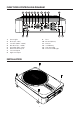
FUNCTIONS CONTROLLING DIAGRAM 1. 2. 3. 4. 5. 6. 7. 8. 1 2 14 13 3 4 5 6 7 8 9 10 12 11 Power Light Phase (00~ 1800) Low Pass (50Hz~ 150Hz) Bass Boost (0 ~ +12dB) Input Gain (Min ~ Max) Remote Control Input Low Level Input High Level Input 9. 10. 11. 12. 13. 14.
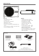
SPECIFICATION GTr 8120 A 72.5 240.0 330.0 ACTIVE SUBWOOFER Subwoofer • Max. Output Power : 300W • Speaker Size : 8.0” • Cone Composition : Aluminium • Magnet Type : Ferrite • Wired Remoted : Included • Enclosure Housing Material : Aluminium Die-cast Sealed • Enclosure Dimension (LxWxH) : 330 x 240 x 73mm • Enclosure Net Weight : 4.09kg Amplifier • Amplifier Technology : Class AB • Normal Output Power (RMS) : 120W • Max.
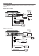
WIRING DIAGRAM Select either Diagram 1 or Diagram 2 for installation. Avoid audio interference by using one audio inputs only.
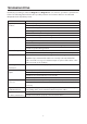
TROUBLESHOOTING Examine if your wiring is similar to Diagram 1 or Diagram 2 in case of device operation or performance failure. The following table indicate other possible problems and solutions. Refer to an authorized Blaupunkt dealer if problem persist.
Designed and engineered by Blaupunkt Competence Centre 1 113 21 014 41 01