Changer CDC A01 Operating and Installation Instructions http://www.blaupunkt.
CONTENTS General Info ............................. 2 Safety Instructions ................... 3 Tips for Safe Operation ............ 3 Condensation .................................. 3 Before Installing the Equipment ......................... 4 Transport Locking Screws ............... 4 Precautions for Installation and Wiring ...................................... 4 Position of the Built-in Anti-Vibration Armature .................... 5 Using the Changer ................... 6 Loading a CD ................
- Disconnect the negative terminal of the battery! When doing so, please observe the vehicle manufacturer’s safety instructions. - Make sure you do not damage vehicle components when drilling any holes. - Depending on the model, your vehicle may differ from the description provided here. We accept no responsibility for any damages due to incorrect installation or connection or for any consequential damages.
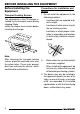
BEFORE INSTALLING THE EQUIPMENT Before Installing the Equipment Precautions for Installation and Wiring Transport Locking Screws 1. Do not install the equipment in the following locations: The mechanism in the CD changer is “locked” by the transport screws during shipping. Make certain to remove these screws before installing the changer. - Locations that are exposed to direct sunlight. - Locations at which warm air exits the car heating system.
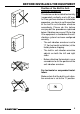
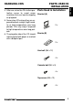
- The anti-vibration armature is set to “0” (for horizontal installation) at the factory before shipping. - The built-in anti-vibration armature adjusts on both the left and right sides. - Before attaching the brackets, use a screwdriver to set the position of the anti-vibration armature. For horizontal or suspended installation: Make certain that the built-in anti-vibration armature is set to the “0” position.
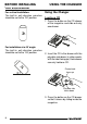
BEFORE INSTALLING THE EQUIPMENT For vertical installation: The built-in anti-vibration armature should be set to the “90” position. USING THE CHANGER Using the Changer Loading a CD 1. Press the button on the CD drawer of the magazine and slide out only one drawer. For installation at a 45° angle: The built-in anti-vibration armature should be set to the “45” position. 2. Insert the CD in the drawer with the playable side down (in other words, with the label facing up). Each drawer can only hold one CD.
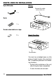
ENGLISH USING THE CHANGER To eject the magazine: Installing the Magazine To eject the magazine, press the Eject button ( ). 1. Slide the cover to the right. Eject button 2. First make certain that the magazine is oriented so that the CD labels face up and so that the magazine faces in the proper direction for installation. Insert the magazine until it engages and thus is locked. When the magazine is used for the very first time, it will not engage until the changer is connected to electrical power.
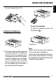
HANDLING CDS Handling CDs things happen, use a pen or a similar object to remove the burs as shown in the figure at right. New CDs The following symptoms often occur when using new CDs: - The CD does not play evenly after being inserted. - The changer changes to the next CD before it has finished playing the first CD. - The changer plays the same CD over and over again. - The system will not play a specific CD.
HANDLING CDS FRANÇAIS Bracket (A) 5. Never store CDs where they are exposed to direct sunlight, high humidity, or high temperatures over long periods. CDs may warp if exposed to high temperatures over long periods. 2x ESPAÑOL 6. The playable side of the CD should not be pasted with paper or marked with a ballpoint pen. ENGLISH Parts Used in Installation Bracke (B) PORTUGUÊS 4. After use, return the CDs to their protective cases to avoid major scratches that can lead to skipping on playback.
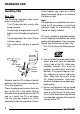
PARTS USED IN INSTALLATION Wiring 8-pin DIN cable Connect this cable to the main unit 1x Seals 1x Double-sided adhesive tape 2x Reset Function Reset button You must use a ballpoint pen or a thin piece of metal to press the reset button. It should be pressed in the following situations: - During initial installation of the unit, after wiring has been completed. - If some functions do not work.
- Make certain that the built-in anti-vibration armature has been set to the “0” position on both the right and left sides. - Lift up the carpet and decide where you want to mount the unit. - Fasten the double-stick tape supplied to the bottoms of the brackets (B) and remove the protective backing from the tape. - Fasten the unit to the floor by pressing it down firmly. - Using the hex bolts (M4 x 5), fasten the left and right brackets (A).
INSTALLATION 4. - Using a knife, cut through the carpet directly above the bolts of the mounting bracket (B). - Replace the carpet in its original position, so that the bolts poke through the carpet. Installation Procedure for Installation on Carpet (Vertical Position) 1. - Make certain that the built-in anti-vibration armature has been set to the “90” vertical installation position on both the right and left sides. - Using the hex bolts (M4 x 5), fasten the left and right brackets (A).
4. - Lift up the carpet and decide where you want to mount the unit. - Using a knife, cut through the carpet directly above the bolts of the mounting bracket (B). - Fasten the double-stick tape supplied to the bottoms of the brackets (B) and remove the protective backing from the tape. - Replace the carpet in its original position, so that the bolts poke through the carpet. PORTUGUÊS ESPAÑOL - Fasten the unit to the floor by pressing it down firmly. FRANÇAIS 2. ENGLISH INSTALLATION 5.
INSTALLATION Installation Procedure for Installation on Carpet (at a 45° Angle) 2. 1. - Fasten the double-stick tape supplied to the bottoms of the brackets (B) and remove the protective backing from the tape. - Set the built-in anti-vibration armature to the 45° position “45” on both the right and left sides. - Using the hex bolts (M4 x 5), fasten the left and right brackets (A). - Lift up the carpet and decide where you want to mount the unit.
INSTALLATION - Replace the carpet in its original position, so that the screws poke through the carpet. ENGLISH 1. - Make certain that the built in anti-vibration armature has been set to the “0” position on both the left and right sides. - Using the hex bolts (M4 x 5), fasten the left and right brackets (A). PORTUGUÊS Position of the built-in anti-vibration armature FRANÇAIS - Using a knife, cut through the carpet directly above the screws of the mounting bracket (B).
INSTALLATION 2. - Determine where you want to install the unit and drill four mounting holes. 3,6 ø 3. - Fasten the CD changer using the tap screws (M5 x 12).
Service numbers / Numéros du service après-vente / Números de servicio / Números de serviço␣ Country: Phone: Fax: WWW: http://www.blaupunkt.