
Manual


— 23 —
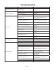
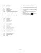
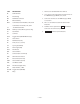
SYM. DESCRIPTION
TB Terminal Block
GL Ground Lug
MC 25A Motor Contactor
OL Overload Relay
MTR 1.5 HP Motor 208-240/480V, 3 PH, 60Hz
1.5 HP Motor 115/230V, 1 PH, 60Hz
CT .150 KVA Transformer
MC-A Auxiliary Contact Block (3-phase only)
FH Fuse Holder
FU 1.6A Fuse
SW-2 Toggle Switch
DS Door Switch
PB Pushbutton (Start)
TR Timer (60-Sec.)
1LT Cycle Light (Amber)
2LT Power Light (Red)
TAS-1 Thermostat
SOL Solenoid Valve
HC Contactor (Elec. Tank Heat)
HTR 3KV Immersion Heater
GC Gas Control (LP or Nat.)
SSOL Solenoid Valve (Steam)
LWC LowWaterCuto
TAS-2 Thermostat (High Limit)
TM Auto Fill Timer (3-Min.)
CR1 Relay
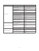
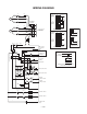
1. All wires are identied with wire markers.
2. Line, motor circuit and immersion heater wires are
#12 AWG Black, type MTW, 105 C, 600 V.
3. Control circuit wires are 16 AWG Red, type MTW,
105 C, 600 V.
4, TR-1 is a cam switch located next to the Timer
Motor TR.
5. Numbers in the square boxes
are Booster
Control circuit connection points.