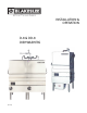
INSTALLATION & OPERATION D-8 & DD-8 DISHWASHERS (01-13)
ELECTRICAL WARNINGS THIS MANUAL HAS BEEN PREPARED FOR PERSONNEL QUALIFIED TO INSTALL ELECTRICAL EQUIPMENT, WHO SHOULD PERFORM THE INITIAL FIELD STARTUP AND ADJUSTMENTS OF THE EQUIPMENT COVERED BY THIS MANUAL. READ THIS MANUAL THOROUGHLY BEFORE OPERATING, INSTALLING OR PERFORMING MAINTENANCE ON THE EQUIPMENT. WARNING: Failure to follow all the instructions in this manual can cause property damage, injury or death.
WARNING: Before performing any service that involves electrical connection or disconnection and/or exposure to electrical components, always perform the Electrical LOCKOUT/TAGOUT Procedure. Disconnect all circuits. Failure to comply with this procedure can cause property damage, injury or death. WARNING: Before removing any sheet metal panels, always perform the Electrical LOCKOUT/TAGOUT Procedure. Be sure all circuits are disconnected.
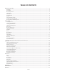
TABLE OF CONTENTS GENERAL DESCRIPTION...............................................................................................................................................................................................................5 Model D-8.................................................................................................................................................................................................................................5 Model DD-8....................
GENERAL DESCRIPTION Model D-8 Control Circuit The Model D-8 door-type commercial dishwasher has a three-sided door or hood that is spring counterbalanced and opens as one unit to provide access to the machine. The machine can be easily modified from a straight- through to a corner unit by simply moving one track rail. If the unit is to be used in a corner, the right side should be positioned toward the wall to allow access to the controls. All units are supplied with a 110 VAC control circuit.
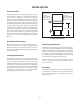
INSTALLATION Visual Inspection Excessive gap on left: Raise left front leg and door will shift to the left Before installing the unit, inspect the shipping container and machine for damage. A damaged container may indicate there is damage to the machine. If there is damage to both the container and machine, do not throw away the container. The dishwasher has been inspected and packed at the factory and is expected to arrive in an undamaged condition.
Electrical Connections Table WARNING Washer Hood Gap Before performing any service that involves electrical connection or disconnection and/or exposure to electrical components, always perform the Electrical LOCKOUT/TAGOUT Procedure. Disconnect all circuits. Failure to comply with this procedure can cause property damage, injury or death. Truss head screws, lockwashers and nuts S/S Refer to the unit’s data plate before making any connections.
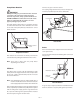
Pump Motor Rotation Connect a ¾" pipe to the line strainer. For a piping run greater than 20 ft, increase the pipe size to insure proper flow pressure at the dishwasher. WARNING Before performing any service that involves electrical connection or disconnection and/or exposure to electrical components, always perform the Electrical LOCKOUT/TAGOUT Procedure. Disconnect all circuits. Failure to comply with this procedure can cause property damage, injury or death.
Electric Heater Gas Heater Before making a gas connection, verify the gas type. A tag is attached to the gas valve that will indicate the correct gas type (L.P. or Natural) to be supplied to the unit. WARNING Before performing any service that involves electrical connection or disconnection and/or exposure to electrical components, always perform the Electrical LOCKOUT/TAGOUT Procedure. Disconnect all circuits. Failure to comply with this procedure can cause property damage, injury or death.
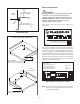
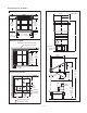
Rough-in Diagrams – Model D-8 STRAIGHT-THROUGH INSTALLATION 30-1/2" WALL 6-1/2" 165mm 15-1/4" 7-1/8" min.** 180mm Tank inside 23-1/2" 595mm Model D-8 Between tracks 20" 510mm Hood outside 25-3/16" 640mm 26" 660mm 30-1/2" 775mm Tank inside 3" 75mm 58" CORNER INSTALLATION RIGHT SIDE OF UNIT ALWAYS FACES WALL Splash guard recommended “Blakeslee” Electric Booster 3" min. 75mm WALL Tank side to rear track 23-3/4" 600mm Tank inside 26" 660mm 25-3/4" 655mm 6" 150 mm 4" min.
Rough-in Diagrams – Model DD-8 WALL 6-1/2" 165mm 7-1/8" min.** 180mm Tank inside 23-1/2" 595mm Between tracks 20" 510mm Hood outside 25-3/16" 640mm 25-3/16" 640mm 52-1/4" 1327mm 56" 1422mm Tank inside Pilot Lighting Model DD-8 25-3/4" 655mm To light the pilot burner: 1. 6" 150 mm 33-5/8" 2-1/2" 65mm 2-1/2" 65mm 4-3/8" 110mm 76" 17" 430mm vert. work clear. L.P. Gas is heavier than air and does not dissipate easily.
Pilot Flame Adjustment Steam Injected Heaters The pilot flame should engulf the tip of the pilot sensing thermocouple. Incoming steam supply line must be connected to the steam connection (line strainer) labeled “incoming steam”. Blakeslee recommends installing a steam shutoff valve and steam regulator (not supplied) close to the dishwasher to aid in servicing. The wash tank water temperature is controlled by the thermostat located inside the control box.
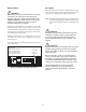
DISPENSER TRANSFORMER K1 FUSE N.O. L1 Ground K1 5* 2 The designated wire connections for the dispensers are found in the control box. #2 is common; the switched side connection is determined by the serial number suffix.
OPERATION Preparing the Dishwasher for Use 1. Close the drain by turning the drain valve handle clockwise as far as it will go. Drain Valve Handle Drain line to sewer 2. Make sure all wash and rinse arms are in position and spin freely. Tighten the lower spindle (turn clockwise) and upper wash rotor nut by hand. 5. Scatter initial charge of detergent into scrap screens. Replenish as needed. This may not be necessary on dishwashers that have an external chemical dispenser. 6.
Automatic Start (Optional) • Stackable ware, such as dishes and trays, should have food debris removed and be placed in manageable stacks. A “buildup” area should be designated for these stacks until dish racks are filled. • Items such as coffee cups, glasses and bowls, do not stack well and should be placed directly into racks for transport. • When racks are filled, they should be kept in the buildup area until they can be washed.
Operating the Dishwasher For units with standard timer, when the hood is opened, the cycle will stop. The cycle will resume at the stopping point when the hood is closed. Once the wash tank has been filled and the detergent added (for units with optional Wash Cycle Timer, set the wash cycle time to 1, 2, 4 or 6 minutes), raise the hood and slide the rack (or racks for DD-8) into the dishwasher.
Standpipe Standpipe Guide Standpipe Screen Standpipe Guide 5. Thoroughly wash and rinse the interior of the dishwasher. Pay special attention to the hood guides and remove any residue. 6. Leave the hood open to allow the interior to dry. 7. If your dishwasher is equipped with an external chemical dispenser, wipe it clean and refill. Follow the instructions from your chemical supplier. 8. Reinstall the standpipe and screen; flip standpipe retainer back in place.
MAINTENANCE Motor Wash Arms No lubrication required. Upper and lower wash arms must turn freely and continue to turn for a few seconds when spun by hand. Wash arm openings may become clogged by food debris if scrap screens are not in place. The wash arms are easily removed for cleaning. Pump No lubrication required. Doors/Hood Rinse Arm No lubrication required.
Pump Motor Overload Protection Water Treatment Wash pump motor protection is provided by thermal overload relay(s) located in the control box. In the event the pump becomes jammed, the motor will draw a higher current and trip the overload relay. Once any jam has been cleared and the impeller turns freely, the overload must be manually reset before the motor will operate. The quality of the water supplied to the dishwasher will greatly affect the maintenance requirements, detergent usage and end results.
TROUBLESHOOTING PROBLEM Pump motor will not start Machine will not start No Tank Heat Wash tank foaming Poor wash results PROBABLE CAUSES CORRECTIVE ACTION Overload tripped Clear pump impeller. Reset relay. Unit not turned ON Place power switch in ON position. Unit not plugged in Plug unit in to an appropriate power receptacle. Power not being supplied to unit Check building circuit breaker or fuses. No power to unit Place power switch in ON position.
PROBLEM Poor rinse results Wash tank not holding water Wash tank will not drain PROBABLE CAUSES CORRECTIVE ACTION Rinse nozzles clogged Clear rinse nozzles. Line strainer clogged Turn off water supply. Clean line strainer screen. Clogged solenoid valve Contact your authorized service provider. Faulty solenoid Contact your authorized service provider. Final rinse booster turned OFF Turn booster ON. Power supply to booster OFF Restore power to booster.
SCHEMATIC OL T2 EQUIPMENT GROUND EQUIPMENT GROUND GL GL HC L2 208 / 240 VAC 1 PHASE 60 HZ SUPPLY LINES L2 HTR T1 L1 T1 OL HC 120 VAC 1 PHASE 60 HZ SUPPLY LINES L1 BLACK L1 HTR WHITE L1 CT EQUIPMENT GROUND OL T3 GL HC L3 L3 HTR T2 L2 T1 L1 208 / 240 / 480 VAC 3 PHASE 60 HZ SUPPLY LINES L2 K1 DISPENSER TRANSFORMER NO K1 TAS-2 FU 15 RINSE CONTROL 6 2 DISPENSER POWER & CONTROL CONNECTIONS (PARTS & WIRING BY OTHERS) 2 1 8 2 CT 16 L1 L2 L1 SW-1 FUSE 7 7 7 BOOST
SYM. DESCRIPTION 1. All wires are identified with wire markers. TB Terminal Block 2. GL Ground Lug Line, motor circuit and immersion heater wires are #12 AWG Black, type MTW, 105 C, 600 V. MC 25A Motor Contactor 3. OL Overload Relay Control circuit wires are 16 AWG Red, type MTW, 105 C, 600 V. MTR 1.5 HP Motor 208-240/480V, 3 PH, 60Hz 4, TR-1 is a cam switch located next to the Timer Motor TR. 5. Numbers in the square boxes Control circuit connection points. 1.
WIRING DIAGRAM OL T3 HTR MC #1 WASH TANK HEATER L3 T2 L2 T1 L1 H1 HC1 OL T3 MC #2 WASH TANK HEATER GL L3 T2 208 / 240 / 480 VAC 3 PHASE 60 HZ SUPPLY LINES L2 L2 208 - 240 VAC SINGLE-PHASE IMMERSION HEATER WIRING #1 WASH TANK HEATER L1 T1 L1 TB 18 TAS-2 FUSE 17 1 7 BOOSTER CONTROL 2 7 DOOR SW THERMAL CYCLE EXTENSION CR 1 3 P B–1 8 ON 4 S W-2 OFF 5 2 4 2 TR CR–1 4 (3 PHASE) 53 4 MC-1-A 54 TR–1 NC COM 5 NO NC 5 TR–2 MC 10 13 L3 MC-1 T3 (1 PHASE) (3 PHASE
SYM. DESCRIPTION 1. All wires are identified with wire markers. TB Terminal Block 2. GL Ground Lug Line, motor circuit and immersion heater wires are #12 AWG Black, type MTW, 105 C, 600 V. MC 25A Motor Contactor 3. OL Overload Relay Control circuit wires are 16 AWG Red, type MTW, 105 C, 600 V. MTR 1.5 HP Motor 208-240/480V, 3 PH, 60Hz 4, TR-1 is a cam switch located next to the Timer Motor TR. 5. Numbers in the square boxes Control circuit connection points. 1.
USA Date of Installation_________________________________ Serial No. Model No. ______________________ ______________________ Limited Warranty Your new Blakeslee dishwashing machine is warranted for one year from date of installation shown above against defective materials and workmanship. If any defects are found within the warranty period, parts, and labor involved with their replacement will be covered free of charge. Service must be performed by a Blakeslee authorized service agency.
Notes — 27 —
1228 Capitol Drive Addison, IL 60101 Phone: 630-532-5021 Fax: 630-532-5020 www.blakesleeinc.com service@blakesleeinc.