SERVICE & OPERATING MANUAL AIR OPERATED DOUBLE DIAPHRAGM PUMP B50 & X50 Full Flow High Pressure Series Stainless Steel This pump is Atex approved for use in potentially explosive atmospheres Group II category 2 Table of Contents Service / Maintenance Log, Recycling 2 Dimensions 3 Performance Curve 3 Technical Data & Temperature limitations 4 Explanation of Pump Nomenclature 4 Principle of Pump Operation 5 Installation guide 5 Important Warnings & Safety Information 6 Troubleshooting 7 Gr
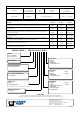
Service / Maintenance Log Date Details Completed RECYCLING Many components of BLAGDON air operated double diaphragm pumps are made of recyclable materials. We encourage pump users to recycle worn out parts and pumps whenever possible, after any hazardous pumped fluids are thoroughly flushed. Contact Information Contact HG-CF-1088 Rev. G - 26.02.13 Phone / Fax No.
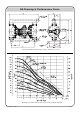
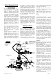
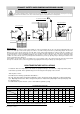
GA Drawing & Performance Curve General Assembly B50 / X5005 Full Flow 2:1 Pump :- All dimensions +/- 3mm B50 Full Flow 2:1 Pump Performance Curve, based on water at ambient temperature HG-CF-1088 Rev. G - 26.02.
TECHNICAL DATA FLUID CONNECTIONS CAPACITY MAX SOLIDS MAX DISCHARGE HEAD DISPLACEMENT/STROKE 2” BSP (F) 0 - 341 Liters/Minute (0 - 75 Gallons/Minute) 6 MM (1/4”) 163 Meters (536 ft) 1.9 Liters (0.42 UK Gallons) MAX.
PRINCIPLE OF PUMP OPERATION This ball valve type diaphragm pump is powered by compressed air and is a 2:1 ratio design. The inner side of one diaphragm chamber is alternately pressurised while simultaneously exhausting the other inner chamber. This causes the diaphragms, which are connected by a common shaft secured by plates to the centres of the diaphragms, to move in a reciprocating action.
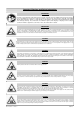
Important Warnings and Safety Information IMPORTANT Read these safety warnings and instructions in this manual completely, before installation and start-up of the pump. It is the responsibility of the purchaser to retain this manual for reference. This manual must be kept with, and supplied with the pump at all times. Failure to comply with the recommendations stated in this manual will damage the pump, and void factory warranty.
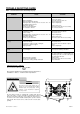
TROUBLE SHOOTING GUIDE NOTE :- Check all solutions before dismantling the pump. PROBLEM CAUSE Pump will not start Air valve assembly malfunction/Siezure Obstructed fluid line. Obstructed diaphragm chamber. Diaphragm failure causing fluid & excessive air to be expelled through the exhaust. Diaphragm seal failure. Air valve system malfunction. Air connected to exhaust. Erratic flow SOLUTION Check carrier for freedom of movement. Clean, oil & replace. Clean line or increase line size. Remove obstruction.
IMPORTANT! Read these instructions completely, before installation and start-up. It is the responsibility of the purchaser to retain this manual for reference. Failure to comply with the recommendations stated in this manual will damage the pump, and void factory warranty. SERVICE The following sections give a general overview on how to service all models of BLAGDON Diaphragm Pumps. For details on individual part numbers, quantities, materials, etc., please consult the parts list supplied with the pump.
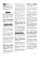
EXHAUST SAFETY WHEN PUMPING HAZARDOUS LIQUIDS WARNING! In the event of diaphragm rupture, pumped material may enter the air end of the pump, and be discharged into the atmosphere. If pumping a product which is hazardous or toxic, the air exhaust must be piped to an appropriate area for safe disposition. Flooded Suction Installation Submerged Installation Suction Lift Installation Exhaust Safety :When a diaphragm fails during operation, pumped liquid can enter and contaminate the air side of the pump.
HG-CF-1088 Rev. G - 26.02.
HG-CF-1088 Rev. G - 26.02.13 PAGE 11 Sectional General Assembly :- B50 / X50 Full Flow 2:1 Metallic Pump Refer to page 10 : Parts List table for item Ref. Nos.
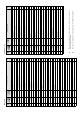
ELASTOMER TABLE REF No. DESCRIPTION 5 O-RING 6 VALVE SEAT 7 BUNA-N NEOPRENE EPDM VITON PTFE QTY G420 G426 G418 G427 G416 4 50-044 50-045 50-046 50-047 - 4 O-RING G457 G458 G459 G460 G461 4 13 DIAPHRAGM 1B004 1B001 1B002 1B003 SEE 63 & 64 2 16 VALVE BALL 1B010 1B056 1B052 1B055 1B053 4 16 VALVE BALL (WTD) 1B079 1B027 1B080 1B088 - 4 14 O-RING G415 G424 G419 G425 G417 2 ELASTOMER TABLE - cont’d REF No.
HG-CF-1088 Rev. G - 26.02.13 PAGE 13 Removal of Diaphragm Shaft :- TECHNICAL NOTES :- Diaphragm Shaft (43) Locknuts (36) Air Chamber Assy. 10 11 13 9 12 After first removing manifolds and air-hoses, remove both outer covers (12), followed by frontplates (9), diaphragms (13), backplates (11) and bumpstops (10). Remove air-chamber assy, by removing nuts & bolts as at (26) & (27). This allows access to locknuts (36) to remove air diaphragm, backplates & thrust washer (37), (22) & (38).
IDEX Pump Technologies (Ireland) Ltd., A Unit of IDEX Corporation, R79, Shannon, Co Clare, IRELAND. TEL. : +353 61 471933 FAX. : +353 61 475046 Web Site : www.blagdonpump.com E-Mail : sales@blagdonpump.com Date : December 01 2009 Des Monaghan, Production & Technical Manager HG-CF-223 (REV 5) HG-CF-1088 Rev. G - 26.02.