SERVICE & OPERATING MANUAL AIR OPERATED DOUBLE DIAPHRAGM PUMP B40 & X40 05 Series Aluminium This pump is Atex approved for use in potentially explosive atmospheres Group II category 2 Table of Contents Service / Maintenance Log, Recycling 2 Dimensions 3 Performance Curve 3 Technical Data & Temperature limitations 4 Explanation of Pump Nomenclature 4 Principle of Pump Operation 5 Installation guide 5 Important Warnings & Safety Information 6 Troubleshooting 7 Grounding the Pump 7 Warran
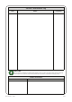
Service / Maintenance Log Date Details Completed RECYCLING Many components of BLAGDON air operated double diaphragm pumps are made of recyclable materials. We encourage pump users to recycle worn out parts and pumps whenever possible, after any hazardous pumped fluids are thoroughly flushed. Contact Information Contact HG-CF-1185 Rev. C - 02.03.11 Phone / Fax No.
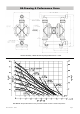
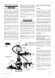
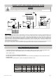
GA Drawing & Performance Curve General Assembly :-B4005 Aluminium pump,all dimensions +/- 3mm B40 Metallic Pump Performance curve, performance based on water at ambient temperature HG-CF-1185 Rev. C - 02.03.
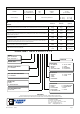
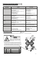
TECHNICAL DATA FLUID CONNECTIONS CAPACITY MAX SOLIDS MAX DISCHARGE HEAD DISPLACEMENT/STROKE 1”1/2 BSP 0 - 320 Litres/Minute (0 - 70 Gallons/Minute) 6 MM (1/4”) 88 Meters (289 ft) 1.2 Litres (0.3 UK Gallons) MAX. WORKING PRESSURE AIR INLET TEMPERATURE LIMITS 8.
PRINCIPLE OF PUMP OPERATION This ball valve type diaphragm pump is powered by compressed air and is a 1:1 ratio design. The inner side of one diaphragm chamber is alternately pressurised while simultaneously exhausting the other inner chamber. This causes the diaphragms, which are connected by a common shaft secured by plates to the centres of the diaphragms, to move in a reciprocating action.
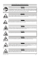
Important Warnings and Safety Information IMPORTANT Read these safety warnings and instructions in this manual completely, before installation and start-up of the pump. It is the responsibility of the purchaser to retain this manual for reference. This manual must be kept with, and supplied with the pump at all times. Failure to comply with the recommendations stated in this manual will damage the pump, and void factory warranty.
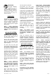
TROUBLE SHOOTING GUIDE NOTE :- Check all solutions before dismantling the pump. PROBLEM Pump will not start CAUSE SOLUTION Air valve assembly malfunction/Seizure Obstructed fluid line. Obstructed diaphragm chamber. Diaphragm failure causing fluid & excessive air to be expelled through the exhaust. Diaphragm seal failure. Air valve system malfunction. Air connected to exhaust. Erratic flow Check carrier for freedom of movement. Clean, oil & replace. Clean line or increase line size. Remove obstruction.
IMPORTANT! Read these instructions completely, before installation and start-up. It is the responsibility of the purchaser to retain this manual for reference. Failure to comply with the recommendations stated in this manual will damage the pump, and void factory warranty. SERVICE The following sections give a general overview on how to service all models of BLAGDON Diaphragm Pumps. For details on individual part numbers, quantities, materials, etc., please consult the parts list supplied with the pump.
EXHAUST SAFETY WHEN PUMPING HAZARDOUS LIQUIDS WARNING! In the event of diaphragm rupture, pumped material may enter the air end of the pump, and be discharged into the atmosphere. If pumping a product which is hazardous or toxic, the air exhaust must be piped to an appropriate area for safe disposition. Flooded Suction Installation Submerged Installation Suction Lift Installation Exhaust Safety :When a diaphragm fails during operation, pumped liquid can enter and contaminate the air side of the pump.
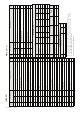
HG-CF-1185 Rev. C - 02.03.11 Page 10 40-037 1A007 40-111 25-060 D337 22 23 24 25 26 G512 40-192 40-264 40-004 30 31 32 33 D391 40-020 21 29 40-012 20 C165 40-228 19 40-266 40-199 18 28 G245 17 27 G189 16 G339 12 25-089 G243 11 15 G242 10 G367 40-259 9 25-091 40-047 8 14 SEE TABLE 7 13 40-131 SEE TABLE 5 SEE TABLE SEE TABLE 4 6 40-230 40-236 3 6 A108 C013 2 ALUMINIUM / COMMON 40-240 ATEX CAT. 2 PART NUMBER 1 REF No.
HG-CF-1185 Rev. C - 02.03.11 Page 11 Outer Seal Lip faces out over 14 15 Inner Seals Lip faces in over, towards holes Lip Seal Positions - B C D E 14 - 15 Nm (10.3 - 13 lbs/ft) 42 - 47 Nm (30 - 35 lbs/ft) 27 Nm (20 lbs/ft) 13.5 - 16 Nm (10 - 12 lbs/ft) 20 - 25 Nm (14.8 - 18.4 lbs/ft Sectional General Assembly :- B4005AA model pump, refer to page 10 Parts List table for Item Ref. Nos.
IDEX Pump Technologies (Ireland) Ltd., A Unit of IDEX Corporation, R79, Shannon, Co Clare, IRELAND. TEL. : +353 61 471933 FAX. : +353 61 475046 Web Site : www.blagdonpump.com E-Mail : sales@blagdonpump.com Date : December 01 2009 Des Monaghan, Production & Technical Manager HG-CF-223 (REV 6) HG-CF-1185 Rev. C - 02.03.