
Instruction Manual


x25fvmdl1sm-rev0411 Page 4
PLEASE NOTE!
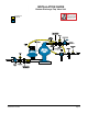
The photos shown in this manual are for general instruction only. Your specic model
may not be shown. Always refer to the parts list and exploded view drawing for your
specic model when installing, disassembling or servicing your pump.
PRINCIPLE OF PUMP OPERATION
This ball valve pump is powered by compressed air and is a 1:1 pressure ratio design.
It alternately pressurizes the inner side of one diaphragm chamber, while simultaneously
exhausting the other inner chamber. This causes the diaphragms, which are connected
by a common rod, to move endwise. Air pressure is applied over the entire surface
of the diaphragm, while liquid is discharged from the opposite side. The diaphragm
operates under a balanced condition during the discharge stroke, which allows the unit
to be operated at discharge heads over 200 feet (61 meters) of water head.
Since the diaphragms are connected by a common rod, secured by plates to the
center of the diaphragms, one diaphragm performs the discharge stroke, while the other
is pulled to perform the suction stroke in the opposite chamber.
For maximum diaphragm life, keep the pump as close to the liquid being pumped
as possible. Positive suction head in excess of 10 feet of liquid (3.048 meters) is not
recommended. For applications with higher suction heads, consult the factory.
Alternate pressuring and exhausting of the diaphragm chamber is performed by
means of an externally mounted, pilot operated, four-way spool type air distribution
valve. When the spool shifts to one end of the valve body, inlet air pressure is applied to
one diaphragm chamber and the other diaphragm chamber exhausts. When the spool
shifts to the opposite end of the valve body, the porting of chambers is reversed. The air
distribution valve spool is moved by an internal pilot valve which alternately pressurizes
one side of the air distribution valve spool, while exhausting the other side. The pilot
valve is shifted at each end of the diaphragm stroke by the diaphragm plate coming in
contact with the end of the pilot valve spool. This pushes it into position for shifting of
the air distribution valve.
The chambers are manifolded together with a suction and discharge check valve for
each chamber, maintaining ow in one direction through the pump.
INSTALLATION & START-UP
Locate the pump as close to the product being pumped as possible, keeping suction
line length and number of ttings to a minimum. Do not reduce line size.
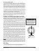
For installations of rigid piping, short exible sections of hose should be installed be-
tween pump and piping. This reduces vibration and strain to the piping system. A surge
suppressor is recommended to further reduce pulsation in ow. Tighten all fasteners
before pump startup.
This pump was tested at the factory prior to shipment and is ready for operation. It
is completely self-priming from a dry start for suction lifts of 17 feet (5.8 meters) or less.
For suction lifts exceeding 17 feet of liquid, ll the chambers with liquid prior to priming.
SERVICE AND OPERATING MANUAL
X25 Metal Flap Valve Pump
Design Level 1
II 2GD T5