
User guide

x25fvdl2sm-rev0213
Model X25 Metallic • 14
www .bla gdon pump .com
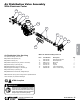
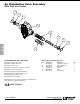
Step 1: With manifolds and outer chambers
removed, remove diaphragm assemblies from
diaphragm rod. DO NOTuseapipewrenchorsimilar
tooltoremoveassemblyfromrod.Flawsintherod
surfacemaydamagebearingsandseal.Softjaws
in a vise are recommended to prevent diaphragm
rod damage.
Step 1.A: NOTE: Notallinnerdiaphragmplates
arethreaded.Somemodelsutilizeathrough hole
intheinnerdiaphragmplate.Ifrequiredtoseparate
diaphragm assembly, place assembly in a vise,
gripping on the exterior cast diameter of theinner
plate.Turntheouterplateclockwisetoseparatethe
assembly.
Alwaysinspect diaphragms for wear cracks or
chemicalattack. Inspectinnerand outerplatesfor
deformities,rustscaleandwear.Inspectintermediate
bearingsforelongationandwear.Inspectdiaphragm
rodforwearormarks.
Clean or repair if appropriate. Replace as required.
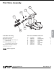
Step 2: Reassembly:Therearetwodifferenttypes
ofdiaphragmplateassembliesutilizedthroughoutthe
Sandpiperproductline:Outerplatewithathreaded
stud, diaphragm, and a threaded inner plate.
Outerplatewithathreadedstud,diaphragm,and
aninnerplatewiththroughhole.Secure threaded
innerplateinavise.Ensurethattheplatesarebeing
installedwiththeouterradiusagainstthediaphragm.
Step 3:Lightlylubricate,withacompatiblematerial,
the inner faces of both outer and inner diaphragm plates
whenusingonnonOverlaydiaphragms(ForEPDM
waterisrecommended).Nolubricationisrequired.
Step 4: Pushthe threaded outer diaphragm
plate through the center hole of the diaphragm.
Note: Most diaphragms are installed with the
naturalbulge out towards the fluid side. S05,
S07,andS10non–metallicunitsareinstalled
withthenatural bulge in towards the air side.
Step 5: Thread or place, outer plate stud into
the inner plate. For threaded inner plates, use a
torquewrench to tighten the assembly together.
Torquevaluesarecalledoutontheexplodedview.
Repeat procedure for second side assembly.
Allowa minimum of 15 minutes to elapse after
torquing,thenre-torquetheassemblytocompensate
forstress relaxation in the clamped assembly.
Step 6: Thread one assembly onto the diaphragm
rodwith sealingwasher(when used)andbumper.
Step 7: Install diaphragm rod assembly
into pump and secure by installing the outer
chamberinplaceandtighteningthecapscrews.
Step 8: On opposite side of pump, thread the
remainingassemblyontothediaphragmrod.Usinga
torquewrench,tightentheassemblytothediaphragm
rod.Aligndiaphragmthroughboltholes,alwaysgoing
forwardpasttherecommendedtorque.Torquevalues
arecalledoutontheexplodedview.NEVER reverse
to align holes, if alignment cannot be achieved
withoutdamage to diaphragm, loosen complete
assemblies, rotate diaphragm and reassemble as
described above.
Step 9: Complete assembly of entire unit.
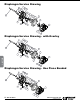
OnePiece Diaphragm Servicing (Bonded PTFE
withintegral plate)TheOnePiecediaphragm has
a threaded stud installed in the integral plate at the
factory. The inner diaphragm plate has a through
holeinsteadofa threaded hole. Place the inner
plateoverthediaphragmstudandthread the rst
diaphragm/innerplateontothediaphragmrodonly
untiltheinnerplatecontactstherod.Donottighten.A
smallamountofgreasemaybeappliedbetweenthe
inner plate and the diaphragm to facilitate assembly.
Insertthediaphragm/rodassemblyintothepump
and install the outer chamber. Turn the pump over
andthreadtheseconddiaphragm/innerplateonto
the diaphragm rod. Turn the diaphragm until the
inner plate contacts the rod and hand tighten the
assembly. Continue tightening until the bolt holes
alignwiththeinnerchamberholes.DO NOT LEAVE
THE ASSEMBLY LOOSE.
IMPORTANT
Read these instructions completely,
before installation and start-up.
It is the responsibility of the
purchaser to retain this manual for
reference. Failure to comply with
the recommendations stated in this
manual will damage the pump, and
void factory warranty.
UNIVERSAL ALL SP
5: WET END