9.00 229 SERVICE & OPERATING MANUAL Original Instructions 4: AIR END 3: EXP VIEW Certified Quality 2: INSTAL & OP 1: PUMP SPECS STATIONARY BOLT DOWN US FEET CAN BE REMOVED. 5: WET END Quality System ISO9001 Certified 6: CERTIFICATES Environmental Management System ISO14001 Certified Model X25 Metallic Flap Valve Pump Design Level 2 IDEX Pump Technologies (Ireland) Ltd. A Unit of IDEX Corporation | R79, Shannon, Co. Clare, IRELAND TEL: +353 61 471933 | FAX: +353 61 475046 | www.blagdonpump.
Safety Information IMPORTANT WARNING Read the safety warnings and instructions in this manual before pump installation and start-up. Failure to comply with the recommendations stated in this manual could damage the pump and void factory warranty. When the pump is used for materials that tend to settle out or solidify, the pump should be flushed after each use to prevent damage. In freezing temperatures the pump should be completely drained between uses.
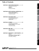
SECTION 4: Air End........................................10 • Air Distribution Valve Assembly • Air Valve with Stroke Indicator Assembly • Pilot Valve Assembly • Intermediate Assembly SECTION 5: Wet end......................................13 • Diaphragm Drawings • Diaphragm Servicing 2: INSTAL & OP 3: EXP VIEW 7: WARRANTY SECTION 7: Warranty & Certificates.....
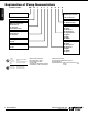
Explanation of Pump Nomenclature 1: PUMP SPECS TYPICAL CODE= X25. 02. C. C. F. T.
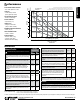
Capacity • 0 to 265 liters per minute (0 to 70 gallons per minute) 7 100 6 5 Solids-Handling • Up to 25.4mm (1 in.) 4 80 60 Heads Up To • 8.8 Kg/cm2 or 88 meters (125 psi or 289 ft. of water) 3 Maximum Operating Pressure • 8.6 bar (125 psi) 2 Displacement/Stroke • .38 liter / .10 Gallon 1 SHIPPING WEIGHT • Aluminum 48 lbs. (21kg) • Cast Iron 76 lbs. (34kg) • Stainless Steel 79 lbs.
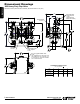
1: PUMP SPECS Dimensional Drawings X25 Heavy Duty Flap Valve Dimensions in inches (metric dimensions in brackets). Dimensional Tolerance .125" (3mm). "C" SUCTION PORT 1" BSP Tapered 1" NPT (OPTIONAL 90 PORT ROTATION) "B" 16.73 425 "A" AIR EXHAUST 3/4" NPT 2.38 60 16.41 417 "D" 15.59 396 14.03 356 8.57 218 6.89 175 2.57 65 AIR INLET 1/2" NPT DISCHARGE PORT 1" BSP Tapered 1" NPT 8.56 217 4X 2.38 60 .72 18 .
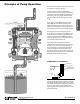
Principle of Pump Operation Air-Operated Double Diaphragm (AODD) pumps are powered by compressed air, nitrogen or natural gas. As inner chamber pressure (P1) exceeds liquid chamber pressure (P2), the rod ⑤ connected diaphragms shift together creating discharge on one side and suction on the opposite side. The discharged and primed liquid’s directions are controlled by the check valves (ball or flap)⑥ orientation. Air Line Discharged Fluid The pump primes as a result of the suction stroke.
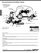
Recommended Installation Guide Available Accessories: 1. Surge Suppressor 2. Filter/Regulator 3. Air Dryer Pipe Connection (Style Optional) 2: INSTAL & OP Unregulated Air Supply to Surge Suppressor Vacuum Gauge Flexible Connector Suction Surge Suppressor 1 Muffler (Optional Piped Exhaust) Check Valve Shut-Off Valve Shut-Off Valve Drain Port 2 Pressure Gauge Flexible Connector Shut-Off Valve Air Inlet 3 Flexible Connector Filter Regulator P/N: 020.V107.
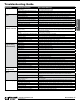
Troubleshooting Guide Pump Cycles Once Pump Will Not Operate / Cycle Pump Cycles and Will Not Prime or No Flow Pump Cycles Running Sluggish / Stalling, Flow Unsatisfactory Product Leaking Through Exhaust Premature Diaphragm Failure Unbalanced Cycling Potential Cause(s): Deadhead (system pressure meets or exceeds air supply pressure). Air valve or intermediate gaskets installed incorrectly. Bent or missing actuator plunger. Pump is over lubricated. Lack of air (line size, PSI, CFM).
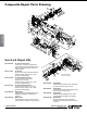
Composite Repair Parts Drawing 27 29 1 26 3 15 56 11 13 57 54 25 9 30 16 4 28 41 46 44 32 12 2 53 7 24 17 42 48 35 53 12 31 46 49 5 47 55 3: EXP VIEW 28 6 20 39 50 46 32 40 43 31 37 23 33 51 52 18 8 41 45 21 53 10 14 53 18 38 36 10 52 51 23 37 36 43 32 22 50 15 56 4 Service & Repair Kits B475.283.000 B476.311.
Item 1 Part Number B031.030.557 2 3 4 B031.203.000 B070.012.170 B095.074.001 B114.007.157 B114.012.010 5 6 7 8 9 10 11 12 13 14 15 16 17 18 19 20 21 22 23 24 25 26 27 28 B115.071.330 B132.019.360 B132.022.360 B135.034.506 B165.134.157 B165.134.558 B170.029.330 B170.033.330 B170.083.330 B170.045.330 B170.063.330 B170.080.330 B170.043.330 B170.006.330 B196.042.157 B196.084.010 B196.043.157 B196.090.010 B196.199.156 B196.199.010 B196.199.110 B255.012.335 B286.008.354 B286.008.356 B286.008.360 B286.008.
3: EXP VIEW Material Codes 000 ����Assembly, sub-assembly; and some purchased items 010 ����Cast Iron 015 ����Ductile Iron 020 ����Ferritic Malleable Iron 080 ����Carbon Steel, AISI B-1112 110 �����Alloy Type 316 Stainless Steel 111 �����Alloy Type 316 Stainless Steel (Electro Polished) 112 �����Alloy C 113 �����Alloy Type 316 Stainless Steel (Hand Polished) 114 �����303 Stainless Steel 115 �����302/304 Stainless Steel 117 �����440-C Stainless Steel (Martensitic) 120 ����416 Stainless Steel (Wrought Marten
Air Distribution Valve Assembly With Aluminum Center 1E 1D 1F 1C 1B 1A 1C 1F 1D 1E 4: AIR END 1F 1E 1C 1D Air Distribution Valve Servicing Main Air Valve Assembly Parts List See repair parts drawing, remove screws. Step 1: Remove hex capscrews (1E). 1B Step 2: Remove end cap (1D). Step 3: Remove spool part of (1A) (caution: do not scratch). Step 4: Press sleeve (1A) from body (1B). Step 5: Inspect bumpers (1C) and o-rings (1F). Step 6: Lightly lubricate O-Rings (1F) on sleeve (1A).
1F 1D Air Distribution Valve Assembly 1E With Cast Iron Center 1F 1E 1C 1D 1B 1A 1D 1C 4: AIR END 1E 1D Air Distribution Valve Servicing See repair parts drawing, remove screws. Step 1: Remove end cap retainer (1E). Step 2: Remove end cap (1C). Step 3: Remove spool part of (1A) (caution, do not scratch). Step 4: Press sleeve (1A) from body (1B). Step 5: Inspect O-Ring (1D) and replace if necessary. Main Air Valve Assembly Parts List Item 1 1A 1B 1C 1D 1E Part Number B031.
Pilot Valve Assembly 4F 4A 4E 4C 4D Pilot Valve Servicing With Pilot Valve removed from pump. Step 1: Remove snap ring (4F). Step 2: Remove sleeve (4B), inspect O-Rings (4C), replace if required. Step 3: Remove spool (4D) from sleeve (4B), inspect O-Rings (4E), replace if required. Step 4: Lightly lubricate O-Rings (4C) and (4E). 4: AIR END 4B pilot valve assembly parts list Item 4 4A 4B 4C 4D 4E 4F Part Number B095.074.001 B095.071.557 B755.025.162 B560.033.
Diaphragm Service Drawing 29 2 54 18 3 20 54 37 15 13 55 16 34 14 39 37 40 17 46 52 19 24 32 24 Diaphragm Service Drawing - with Overlay 29 2 54 18 3 20 54 37 15 13 55 16 34 14 39 37 40 17 46 52 5: WET END 19 44 24 32 24 Diaphragm Service Drawing - One Piece Bonded 29 2 54 18 3 20 54 37 15 13 55 16 34 14 37 40 46 52 17 19 24 32 13 • Model X25 Metallic 24 www . blagdonpump .
Diaphragm Servicing Step 1: With manifolds and outer chambers removed, remove diaphragm assemblies from diaphragm rod. DO NOT use a pipe wrench or similar tool to remove assembly from rod. Flaws in the rod surface may damage bearings and seal. Soft jaws in a vise are recommended to prevent diaphragm rod damage. Step 1.A: NOTE: Not all inner diaphragm plates are threaded. Some models utilize a through hole in the inner diaphragm plate.
EC Declaration of Conformity Manufacturer: IDEX Pump Technologies (Ireland) Ltd., A Unit of IDEX Corporation R79, Shannon, Co Clare, Ireland Certifies that Air-Operated Double Diaphragm Pump Series: B75, X25, X40, X50, X75, AVB75, AVX75 and Pulsation Dampener models: PD25M, PD40M, PD50M & PD80M comply with comply with the European Community Directive 2006/42/EC on Machinery, according to Annex VIII.
EC Declaration of Conformity In accordance with ATEX Directive 94/9/EC, Equipment intended for use in potentially explosive environments. Manufacturer: IDEX Pump Technologies (Ireland) Ltd., A Unit of IDEX Corporation, R79, Shannon, Co Clare, IRELAND. AODD Pumps Equipped with Aluminium Type Examination Certificate: KEMA 09ATEX0072 X AODD (Air-Operated Double Diaphragm) Pumps EC Type Examination Certificate No. Pumps: KEMA 09ATEX0071 X KEMA Quality B.V.