
Blade Theory Type W Manual - US


9
EN
Post-Flight Inspection
Cleaning Make sure the battery is not connected before cleaning. Remove dust and debris with a soft brush or a dry lint free cloth.
Airframe Check the airframe for any cracks or other damage. Minor repairs to the foam can be made using CA or epoxy. Badly damaged parts should be replaced.
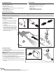
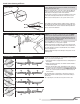
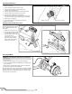
Control Linkages
Make sure the control horns are secure. Make sure the control rods are secure in the control horns. Make sure the clevises are tight and the silicone
retainers are in place.
Wiring Make sure wiring does not contact moving parts. Replace damaged wiring and loose connectors.
Fasteners
Make sure there are no loose screws, other fasteners or connectors. Do not over tighten metal screws in plastic parts. Tighten screw so parts are
mated together, then turn screw only 1/8th of a turn more.
Propeller Make sure there is no damage to the propeller blades. Damage includes cracks, burrs, chips or scratches. Replace damaged parts before the next fl ight.
Receiver
Make sure the AR636 receiver is securely attached to the frame. Replace the double-sided tape when necessary. The aircraft will crash if the
receiver separates from the frame.
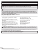
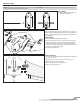
Using the Video Transmitter
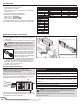
CH 1 CH 2 CH 3 CH 4 CH 5 CH 6 CH 7 CH 8
1. Band A 5865 5845 5825 5805 5785 5765 5745 5725
2. Band B 5733 5725 5771 5790 5809 5828 5847 5866
3. Band E** 5705 5685 5665 N/A 5885 5905 N/A N/A
4. FS/IRC 5740 5760 5780 5800 5820 5840 5860 5880
5. RaceBand 5658 5695 5732 5769 5806 5843 5880 5917
** E band Channels 4, 7 and 8 have been removed to prevent transmitting outside of
designated Amateur radio frequencies
Band Number
Channel Number
Available Frequencies (mHz)
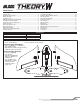
Display Locked
Channel Selection
Select desired channel
Select desired band
Band Selection
Hold for 2 seconds
Programming Flowchart
Hold for 2 seconds
Hold for 2 seconds
Channel Select
Button
Dot Indicating
Band Selected
Digital Display
If you are operating this product in North America, you are
required to have an Amateur Radio (HAM) license.
Visit www.arrl.org for more information.
NOTICE: Never power on the video transmitter without the antenna installed.
Powering on without the antenna will damage the video transmitter. This
damage is not covered under warranty.
The video transmitter is located under the battery compartment.
At power up the digital display will fl ash 2 numbers repeatedly, indicating
it is locked. The number with the “dot” is the selected BAND (1.-5.), the
second number is the channel (1-8).
Channel Selection:
1. To unlock the display push and hold the
Channel Select button for 2 seconds.
2. Press the button to cycle through the channels (1-8).
3. Press and hold the button for 2 seconds to exit Channel Select.
If you are changing bands, proceed to Step 3 of the Band Selection section.
4. Press and hold the button again for 2 seconds to exit and lock the display.
Band Selection:
1. Press and hold the button for 2 seconds to enter Channel Select.
2. Press and hold the button again for 2 seconds to switch from
Channel Select to Band select.
3. Press the button to cycle through the Bands (1-5).
4. Press and hold the button for 2 seconds to exit and lock the display.
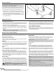
NOTICE: The small hole at the front of the airframe is to provide cooling
airfl ow to the video transmitter. DO NOT cover or allow this hole to be clogged
with debris as the video transmitter may overheat.
Low Voltage Cutoff (LVC)
When a Li-Po battery is discharged below 3V per cell, it will not hold a charge.
The ESC protects the fl ight battery from over-discharge using Low Voltage Cutoff
(LVC). Before the battery charge decreases too much, LVC removes power sup-
plied to the motor. Power to the motor pulses, showing that some battery power is
reserved for fl ight control and safe landing.
Disconnect and remove the Li-Po battery from the aircraft after use to prevent
trickle discharge. Charge your Li-Po battery to about half capacity before storage.
During storage, make sure the battery charge does not fall below 3V per cell. LVC
does not prevent the battery from over-discharge during storage.
NOTICE: Repeated fl ying to LVC will damage the battery.
Repairs
Repairs to the foam can be made using virtually any adhesive (hot glue, CA,
epoxy, etc). When parts are not repairable, see the Parts List for ordering a
replacement airframe. For a listing of all replacement components and optional
parts, refer to the list at the end of this manual.
NOTICE: When using cyanoacrylate (CA) adhesive to join or repair the airframe,
DO NOT allow the adhesive to contact or get close to the fpv camera lens. The
vapors from the adhesive will permanently fog the camera lens.