
Blade Theory Type W Manual - US


6
EN
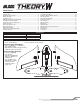
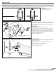
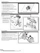
1. Remove the center section cover.
2. Insert the fl ight battery as shown. Secure the battery with the hook
and loop straps.
3. Connect the battery connector to the ESC power lead, noting correct polarity.
CAUTION: Connecting the battery to the ESC with reversed
polarity will cause damage to the ESC, the battery or both.
Damage caused by incorrectly connecting the battery is not covered
under warranty.
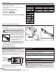
The ESC utilizes an XT-60 connector. If your
fl ight battery uses an EC3™ connector you may
either use an adapter, available in the Optional
Parts list, or you may connect the EC3 connec-
tor directly to the XT-60. The round negative
terminal of the EC3 fi ts in the angled negative
terminal of the XT-60 as shown.
4. Keep the aircraft level, out of the wind and immobile for approximately
5 seconds, until the receiver initializes. The ESC will emit a series of
tones and the LED on the receiver will light. If the receiver does not
fully initialize, re-bind the receiver to your transmitter as shown in the
Transmitter and Receiver Binding section.
5. Replace the center section cover.
Flight Battery Installation and ESC Arming
NOTICE: Do not install the propeller and propeller adapter to
the motor shaft prior to binding to prevent injury or damage due to
unexpected motor startup during binding.
Binding is the process of programming the receiver to recognize the GUID
(Globally Unique Identifi er) code of a single specifi c transmitter. You need
to ‘bind’ your chosen Spektrum
™
DSM2
®
/DSMX
®
technology equipped
aircraft transmitter to the receiver for proper operation.
If you encounter problems, obey binding instructions and refer to your
transmitter troubleshooting guide for other instructions. If needed, contact
the appropriate Horizon Product Support offi ce.
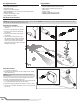
Transmitter and Receiver Binding
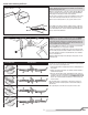
Binding Procedure
1. Insert the bind plug in the BIND port on the receiver.
2. Connect the battery connector to the ESC power lead. The orange LED on the receiver
fl ashes rapidly, indicating the receiver is in bind mode.
3. Lower the throttle stick to the lowest position. Set all trims to the center position.
4. Follow the procedures of your specifi c transmitter to enter Bind Mode. The system will
connect within a few seconds. Binding is complete when the orange LED on the receiver
glows solid.
5. Remove the bind plug from the BIND/PROG port, and store it in a convenient place.
6. Disconnect the battery from the ESC power lead.
7. Power off the transmitter.
BIND
Throttle
Right Elevon
Left Elevon
LED
WARNING: You must move the throttle to the LOW/OFF position prior to binding.
Failure to do so may cause the motor to start unexpectedly during binding, which
could result in damage to property and injury.
NOTICE: Remove the bind plug to prevent the system from entering bind mode the next
time the power is turned on.
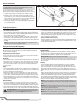
Program Your Transmitter
1. Start with a clean model memory slot.
2. Set the model type to “Airplane.”
3. Assign channel 5 (Gear) to a 3-position switch. In the table at left,
switch B is used.
4. Leave all other settings at the default values.
Switch B will now control the fl ight mode function.
Switch position 0 = Launch Mode
Switch position 1 = Intermediate Mode
Switch position 2 = Experienced Mode
If, after fl ying the aircraft, more or less exponential or dual rate values
are desired, those may be adjusted up or down to suit your fl ying style.
Transmitter Setup
Timer
Mode Count Down
Time 8:00
Start Throttle Out
Over 25%
One Time Inhibit
FUNCTION LISTSETUP LIST
F-Mode Setup
Switch 1 Inhibit
Switch 2 Inhibit
Model Type
Airplane
Channel Assign
Channel Input Confi g
1 Throttle
2 Aileron
3 Elevator
4 Rudder
5 Gear Switch B
6 Aux 1
Frame Rate
22ms
DSMX
DX6, DX7 (Gen 2), DX8 (Gen 2), DX9, DX18, DX20