
Scimitar 215 Manual


7
EN
Band
CH 1 CH 2 CH 3 CH 4 CH 5 CH 6 CH 7 CH 8
FS/IRC 5740 5760 5780 5800 5820 5840 5860 5880
Band E 5705 5685 5665 5665 5885 5905 5905 5905
Band A 5865 5845 5825 5805 5785 5765 5745 5725
RaceBand 5658 5695 5732 5769 5806 5843 5880 5917
Band B 5733 5752 5771 5790 5809 5828 5847 5866
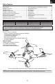
Using the Video Transmitter
Preparing the Scimitar 215 Quadcopter for Flight
1. Before each fl ight, ALWAYS power on the transmitter before connecting the fl ight battery to the quadcopter. After each
fl ight, disconnect the fl ight battery from the quadcopter before powering off the transmitter.
NOTICE: Connecting the fl ight battery before powering on the transmitter can start the binding process. Please see the
Transmitter and Receiver Binding section of this manual for more information.
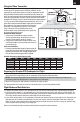
2. When the ESC beeps, the fl ight controller is initialized and ready for fl ight.
The fl ight controller will not arm the motors until the throttle stick is in the lowest possible position.
• In angle mode (switch position 0 ), the quadcopter will self-level and has a bank angle limit of approximately 60 degrees.
• In air mode (switch position 1), the quadcopter will not self-level and does not have a bank angle limit. At low throttle, the
fl ight controller will continue to stabilize the quadcopter to hold whatever attitude was last commanded. This mode is use-
ful for fl ying smooth aerobatic maneuvers at both high and low throttle settings.
• In acro mode (switch position 2 ), the quadcopter will not self-level and does not have a bank angle limit. At low throttle, the
fl ight controller will not stabilize the quadcopter. The pilot must actively control the quadcopter to maintain a desired at-
titude. This mode is most preferred when immediate changes in altitude are desired, such as in racing. Use rates and expo
to tune the performance according to your fl ying style.
Refer to the Transmitter Setup for transmitter switch selection and specifi c setup information.
Flight Mode and Rate Selection
Available Frequencies, North America (mHz)
Consult local laws and ordinances before operating FPV equipment.
In some areas, FPV operation may be limited or prohibited. You are
responsible for operating this product in a legal and responsible manner.
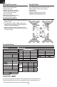
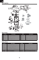
See the Available Frequency table to fi nd the desired video channel and
band. The video transmitter channel and band are changed using the buttons
on the top of the quadcopter, as shown. There are two rows of LEDs visible
through the LED window. The row of red LEDs indicates the channel selected
(1-8). The row of blue LEDs indicates the selected band (A, B, E, F, R). The
green LEDs indicate the video transmitter output power level selected.
Only change the video channel and band when the video
transmitter is not transmitting a signal or is in Pit Mode.
If any of the green LEDs are glowing solid, see the
directions below to stop transmitting a video signal prior
to changing the channel or band.
Channel and Band Selection:
1. A short press of button B will change channels.
Quickly press and release the button once for each
channel until the desired channel is reached.
2. A long press of button B will change the band. Press
and hold button B for several seconds and release for
each band change.
Power Level Selection
†
:
1. Press and hold button A to change the power output. All
green LEDs off means RF is off, one fl ashing green LED is
Pit Mode, one solid green LED is 25mW, two solid green
LEDs is 200mW, three solid green LEDs is 600mW.
LED window
Buttons
8
7
6
5
4
3
2
1
R
F
E
B
A
Button B
Button A
Channels
Bands*
Power
Level