
360 CFX 3S Manual

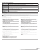

To use the Spektrum
™
DXe transmitter, download the Blade
®
360 CFX 3S DXe model
setup available at www.spektrumrc.com or use the appropriate programming cable
and the PC or mobile app to program the transmitter.
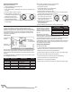
D/R & Expo
Chan Sw Pos D/R Expo
AILE
0 100 0
185 0
ELEV
0 100 0
185 0
RUDD
0 100 0
185 0
Timer
Down Timer 4:00
Switch THR CUT
ADJUST LIST
SETUP LIST
DX6i
Throttle Curve
Switch Pos (F Mode) Pos 1 Pos 2 Pos 3 Pos 4 Pos 5
NORM 0 50 50 50 50
STUNT* 65 65 65 65 65
TRAVEL ADJ
Channel Travel
THRO 100/100
AILE 100/100
ELEV 100/100
RUDD 100/100
GYRO 100/100
PITC 100/100
REVERSE
Channel Direction
THRO N
AILE N
ELEV N
RUDD N
GYRO N
PITC R
GYRO
RATE SW-F.MODE
0 60% NORM 0
1 50% STUNT 1
Modulation Type
AUTO DSMX-ENABLE
D/R COMBI
D/R SW AILE
Model Type HELI
Swash Type 1 servo 90
Pitch Curve
Switch Pos (F Mode) Pos 1 Pos 2 Pos 3 Pos 4 Pos 5
NORM 25 37 50 75 100
STUNT 0 25 50 75 100
HOLD 25 37 50 75 100
4
EN
Low Voltage Cuto (LVC)
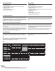
Transmitter Setup
The Blade 360 CFX 3S Electronic Speed Controller (ESC) utilizes a head speed
governor to maintain a constant head speed during fl ight. The governor will work
to maintain a constant head speed throughout maneuvers and the discharge cycle
of the fl ight battery.
The throttle position determines the requested head speed, and although throttle
curves are still used, they will be a constant value; all positions of the curve are
set to the same value. The lowest position of the normal fl ight mode throttle curve
must be set to 0 to ensure the motor can be disabled.
The default throttle curve settings listed in the transmitter setup tables should be
acceptable to most pilots and we recommend starting with these values. If you
feel an adjustment is necessary after a few fl ights, adjust the throttle percentage
for the desired fl ight mode. We recommend making small changes of 5% to fi nd
your preferred head speed.
Remember the throttle position on the transmitter is simply requesting a specifi c
head speed and this is not related to the actual motor power percentage.
Electronic Speed Controller Governor Operation
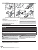
First Flight Preparation
• Remove and inspect contents
• Charge the fl ight battery
• Install the fl ight battery in the helicopter (once it has been fully charged)
• Program your computer transmitter
• Bind your transmitter
• Familiarize yourself with the controls
• Find a suitable area for fl ying
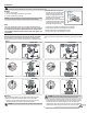
Flying Checklist
❏ Always turn the transmitter on fi rst
❏ Turn throttle hold On
❏ Plug the fl ight battery into the lead from the ESC
❏ Allow the ESC to initialize and arm properly
❏ Perform control test
❏ Place the model onto fl at ground at least 10 meters from the pilot. Ensure the
area is free from obstructions
❏ Fly the model
❏ Land the model
❏ Unplug the fl ight battery from the ESC
❏ Always turn the transmitter off last
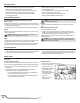
Program your transmitter before attempting to bind or fl y the helicopter. Always
start by creating a new model in the transmitter to ensure no existing settings
are inadvertently used. Transmitter programming values are shown below for the
Spektrum Transmitters. The fi les for models using Spektrum
™
transmitters with
Spektrum AirWare
™
software are also available for download online at
www.spektrumrc.com.
DXe
The ESC will continuously lower power to the motor until complete shutdown
when the battery reaches 9V under load. This helps prevent over-discharge of the
Li-Po battery. Land immediately when the ESC activates LVC. Continuing to fl y after
LVC can damage the battery, cause a crash or both. Crash damage and batteries
damaged due to over-discharge are not covered under warranty.
Repeatedly fl ying the helicopter until LVC activates will damage the helicopter battery.
Disconnect and remove the Li-Po battery from the aircraft after use to prevent trickle
discharge. During storage, make sure the battery charge does not fall below 3V per
cell.