® Instruction Manual Bedienungsanleitung Manuel d’utilisation Manuale di Istruzioni
NOTICE All instructions, warranties and other collateral documents are subject to change at the sole discretion of Horizon Hobby, LLC. For up-to-date product literature, visit horizonhobby.com and click on the support tab for this product.
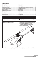
Table of Contents First Flight Preparation ...................................................... 4 Flying Checklist ................................................................ 4 Transmitter Setup Table (BNF) ........................................... 4 Installing the Flight Battery ............................................... 7 Transmitter and Receiver Binding...................................... 7 SAFE® Technology ............................................................
First Flight Preparation Flying Checklist • • • • ❏ Always turn the transmitter on first ❏ Plug the flight battery into the lead from the ESC ❏ Allow the receiver and ESC to initialize and arm properly ❏ Fly the model ❏ Land the model ❏ Unplug the flight battery from the ESC ❏ Always turn the transmitter off last Remove and inspect contents Begin charging the flight battery Program your computer transmitter Install the flight battery in the helicopter (once it has been fully charged) • Bind your transmitter
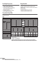
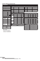
DX7s, DX8 SYSTEM SETUP FUNCTION LIST Model Type HELI Servo Setup Chan Travel THR 100/100 AIL 100/100 ELE 100/100 RUD 100/100 Swash Type 1 servo Normal F-Mode Setup Flight Mode F Mode Hold Hold SW Select Trainer F Mode Gyro Mix Hold Knob Aux 2 Gear INH INH INH INH Frame Rate 11ms DSMX D/R & Expo Switch Pos Chan (Ail D/R) 0 AILE 1 2 0 ELEV 1 2 0 RUDD 1 2 Reverse Normal Normal Normal Normal D/R 100/100 100/100 75/75 100/100 100/100 75/75 100/100 100/100 75/75 Expo +25 +25 +25 +25 +25 +25 +25 +25 +25
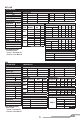
DX7 (G2), DX8 (G2), DX9, DX18, DX20 SYSTEM SETUP FUNCTION LIST Model Type HELI Servo Setup Chan Travel THR 100/100 AIL 100/100 ELE 100/100 RUD 100/100 GER 100/100 Swash Type Normal F-Mode Setup Switch 1 Switch B Switch 2 Inhibit Hold Switch Switch H 1 0 Channel Assign Channel Input Config 1 Throttle 2 Aileron 3 Elevator 4 Rudder 5 Gear Switch B 6 Collective 7 AUX 2 Switch I Frame Rate 11ms DSMX D/R & Expo Chan Sw (F) Pos 0 AILE 1 2 0 1 ELEV 2 0 RUDD 1 2 Reverse Normal Normal Normal Normal Normal D/R 10
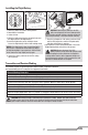
Installing the Flight Battery 1 2 5 1. Lower the throttle stick to the lowest position. 2. Power ON the transmitter. 3. Center all trims. 4. Attach the hook material to the helicopter frame and the loop material to the flight battery. 5. Install the flight battery on the helicopter frame. Secure the flight battery with the hook and loop strap. CAUTION: Connecting the battery to the ESC with reversed polarity will cause damage to the ESC, the battery or both.
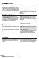
Technology Revolutionary SAFE® (Sensor Assisted Flight Envelope) technology uses an innovative combination of multi-axis sensors and software that allows model aircraft to know its position relative to the horizon. This spatial awareness is utilized to create a controlled flight envelope the aircraft can use to maintain a safe region of bank and pitch angles so you can fly more safely.
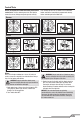
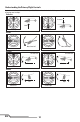
Control Tests Ensure the throttle hold is ON when doing the direction control tests. Test the controls prior to the first flight to ensure the servos, linkages and parts operate correctly. If the controls do not react as shown in the illustrations below, confirm the transmitter is programmed correctly before continuing on to the Motor test.
Understanding the Primary Flight Controls If you are not familiar with the controls of your 250 CFX, take a few minutes to familiarize yourself with them before attempting your first flight.
Flying the 250 CFX Consult your local laws and ordinances before choosing a location to fly your aircraft. We recommend flying your aircraft outside in calm winds or inside a large gymnasium. Always avoid flying near houses, trees, wires and buildings. You should also be careful to avoid flying in areas where there are many people, such as busy parks, schoolyards or soccer fields. It is best to fly from a smooth flat surface as this will allow the model to slide without tipping over.
4. Cyclic Response (Default 100%) Higher cyclic response will result in a more aggressive cyclic response. Lower cyclic response will result in a less aggressive cyclic response. 5. Tailrotor P Gain Adjustment (Default 100%) Higher gain will result in greater stability. Setting the gain too high may result in random twitches if your model has an excessive level of vibration. High frequency oscillations may also occur if the gain is set too high. Lower gain may result in a decrease in stability.
The current gain value for the selected parameter is indicated on the Flight Log screen and by the angle of the swashplate (forward or backward) as shown in the table at the right. Move the cyclic stick forward or backward to adjust the gain value. Moving the stick forward will increase the gain value. Moving the stick backward will decrease the gain value. It is always best to adjust one gain at a time. Make small adjustments (5% or less) and test fly the model to evaluate the adjustments that were made.
Trim Flight Perform this procedure if the model is not performing well or has been recently rebuilt from a crash. The trim flight procedure was performed during the factory test flight and only needs to be performed if you notice the model is not returning to level consistently or if the model does not remain still during stationary pirouettes. The trim flight is used to determine the optimal settings for SAFE® technology during flight. The trim flight must be performed in calm conditions.
Calibration Procedure If the Blade 250 CFX is experiencing drift issues after completing the trim flight procedure located at www.bladehelis.com, perform the following calibration. The calibration procedure may also be needed following crash repairs. WARNING: Before beginning the calibration procedure, disconnect the main motor and tail motor leads to prevent accidental motor startup during calibration. To perform the calibration procedure: 1. Ensure the surface used for calibration is level. 2.
Post-Flight Inspection and Maintenance Checklist √ Make sure the plastic ball link holds the control ball, but is not tight (binding) on the ball. When a link is too loose on the ball, it can separate from the ball during flight and cause a crash. Replace worn ball links before they fail. Make sure the battery is not connected before cleaning. Remove dust and debris with a soft brush or Cleaning a dry, lint-free cloth.
Problem Possible Cause Solution The bind plug was not removed from the receiver after binding Less than a 5-second wait between first powering on the transmitter and connecting the LED on the receiver flashes flight battery to the helicopter rapidly and the helicopter The helicopter is bound to a will not respond to the different model memory transmitter (after binding) (ModelMatch™ transmitters only) Flight battery or transmitter battery charge is too low Aircraft or transmitter is too close to large metal
Exploded View 19 1 2 20 19 6 23 4 17 7 15 24 24 19 29 23 24 30 36 21 13 9 14 21 12 31 38 34 38 8 5 3 28 10 20 18 16 11 38 23 29 35 37 32 28 30 25 Parts Listings 1 2 3 4 5 6 7 8 9 10 11 12 13 14 15 16 17 Part # BLH1501 BLH1502 BLH1504 BLH1505 BLH1512 BLH1513 BLH1514 BLH1515 BLH4484 BLH2020 BLH2021 BLH4481RE BLH4481YE BLH4482 BLH4483 BLH4501C BLH4502 18 BLH4503 19 BLH4504 EN Description Main rotor head: Blade 230s Spindle set: Blade 230s Main rotor head linkage set: Bl
Optional Parts Part # Description Part # Description EFLB13503S30 BLH1501A BLH1505A BLH1513A BLH1519A BLH1578 BLH1610 BLH4612 EFLA261 1350mAh 3S 11.1V 30C LiPo, 13AWG EC3 Aluminum Main Rotor head : 230 S Aluminum Swashplate : 230 S Aluminum Tail case set : 230 S Aluminum Blade grips : 230 S Rotor Head Assembly: 230S Pinion Gear, 10T 0.5M: B450, B400 Main Motor Mount: 300 CFX Micro/Mini Heli Tool Assortment, 6 pc EFLC3016 EFLC4030 EFLH1000 3S DC Li-Po Balancing Charger: 3.5A 3.
If you do not have internet access, please contact Horizon Product Support to obtain a RMA number along with instructions for submitting your product for service. When calling Horizon, you will be asked to provide your complete name, street address, email address and phone number where you can be reached during business hours. When sending product into Horizon, please include your RMA number, a list of the included items, and a brief summary of the problem.
FCC Information This device complies with part 15 of the FCC rules. Operation is subject to the following two conditions: (1) This device may not cause harmful interference, and (2) this device must accept any interference received, including interference that may cause undesired operation. CAUTION: Changes or modifications not expressly approved by the party responsible for compliance could void the user’s authority to operate the equipment.
©2016 Horizon Hobby, LLC. Blade, E-flite, Bind-N-Fly, the BNF logo, DSM, DSM2, DSMX, AS3X, SAFE, the SAFE logo, EC3 and ModelMatch are trademarks or registered trademarks of Horizon Hobby, LLC. The Spektrum trademark is used with permission of Bachmann Industries, Inc. Futaba is a registered trademark of Futaba Denshi Kogyo Kabushiki Kaisha Corporation of Japan All other trademarks, service marks and logos are property of their respective owners. Patents pending.