
User Manual


center for the majority of the flight.
It is possible the trim flight may not record the correct values due to excessive vibration, flying in wind or
the model not staying level. In certain cases, short hops may work better. Try the 30 second level flight
without corrections mentioned above first, then shorten the hops to look for improvements.
If the model performs poorly or does not level properly after the trim flight, retry the trim flight procedure. If
the problem persists, inspect the model for damaged components, a bent shaft or anything that may
result in increased vibration.
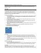
Servo Arm Linkage Ball
The linkage ball must be mounted in the 3
rd
hole out from center. The linkage ball is installed on the inside
of the servo arm for the fore/aft cyclic servo and on the outside of the servo arm on the left/right cyclic
servo.
Servo Calibration and Swashplate Linkage Adjustment
1. Disconnect 2 of the 3 main motor wires and disconnect the tail rotor
motor from the ESC.
2. Lower the throttle stick to the lowest position. If your transmitter utilizes
mechanical trims (like the included RTF transmitter), set the throttle trim
to the highest position. Set all other trims to the center position.
3. Power ON the transmitter.
4. Install the flight battery on the helicopter frame. Secure the flight battery
with the hook and loop strap.
5. Connect the battery connector to the ESC.
6. Place the helicopter on a flat surface and leave it still until the motor
beeps twice and the blue ESC LED glows solid, indicating initialization
is complete.
7. Place a servo arm on the fore/aft servo in any location.
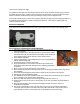
8. Move and hold the left stick to the bottom left corner and the right stick to the bottom right corner.
See illustration.
9. Press and hold the bind/panic switch until the fore/aft cyclic servo moves several times.
10. Release the sticks and bind/panic switch.
11. The AR636H is now in servo calibration mode. If the fore/aft servo arm does not move, swap the
servo connectors in the receiver before proceeding.
12. Move the rudder stick either full left or full right to reset both servo trims to 0.
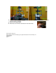
13. Install the servo arms on the servos, ensuring they are as close as possible to perpendicular to
the servos.
14. Move the elevator/aileron stick up/down then left/right until both servos are as close to
perpendicular as possible.
15. The range of adjustment is small. If the arm does not move far enough with the adjustment,
remove the arm and rotate it one spline. Move the rudder stick full left or right to reset and try
again. Always remember to verify both servos are perpendicular before proceeding.