
User Manual


8
EN
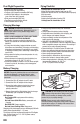
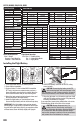
Panic Mode Operation
Bind / I Button
Pressed = Panic Mode On
Released = Panic Mode Off
1. Lower the throttle stick to the lowest position.
2. Power ON the transmitter.
3. Center all trims. For the included MLP6 transmitter
(RTF only), the trims are centered when you hear a
longer tone while pressing the trim button. Move the
trim in both directions until you hear the long tone.
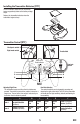
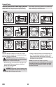
4. Attach the hook material to the helicopter frame and
the loop material to the fl ight battery.
5. Install the fl ight battery on the helicopter frame.
Secure the fl ight battery with the hook and loop strap.
IMPORTANT: If the fl ight battery hook and loop strap is
pulled too tight, it may result in a vibration or the tail rotor
may drift to the right during fl ight. If you experience either
of these issues, loosen the strap slightly and fl y again.
6. Connect the battery connector to the ESC, noting
correct polarity.
CAUTION: Connecting the battery to the ESC
with reversed polarity will cause damage to the
ESC, the battery or both. Damage caused by incorrectly
connecting the battery is not covered under warranty.
7. Place the helicopter on a fl at surface and leave it still
until the ESC beeps and the receiver LED glows solid,
indicating initialization is complete.
If you experience issues during initialization, refer to the
Troubleshooting Guide at the back of the manual.
CAUTION: Always disconnect the Li-Po
battery from the aircraft when not fl ying to
avoid over-discharging the battery. Batteries discharged
to a voltage lower than the lowest approved voltage
may become damaged, resulting in loss of performance
and potential fi re when batteries are charged.
Installing the Flight Battery
1 2
3
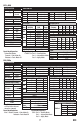
Flight Mode Operation
Sw B: Pos 0 = Stability Mode
Pos 1 = Intermediate Mode
Pos 2 = Agility Mode
D/R & Expo Throttle Curve
Chan Sw (F) Pos D/R Expo Sw (B) Pos Pt 1 Pt 2 Pt 3 Pt 4 Pt 5
AILE
0 100/100 +25 N 0 48 66 75 80
1 75/75 +25 1 80 80 80 80 80
2 75/75 +25 2 100 100 100 100 100
ELEV
0 100/100 +25 Pitch Curve
1 75/75 +25
Sw (B) Pos Pt 1 Pt 2 Pt 3 Pt 4 Pt 5
2 75/75 +25 N 40 45 50 75 100
RUDD
0 100/100 +25 1 0 25 50 75 100
1 75/75 +25 2 0 25 50 75 100
2 75/75 +25 HOLD 40 45 50 75 100
Gyro
Inhibit
Chan Travel Reverse
THR 100/100 Normal
AIL 100/100 Normal
ELE 100/100 Normal
RUD 100/100 Normal
GER 100/100 Normal
Chan Travel Reverse
PIT 100/100 Normal
AX2 100/100 Normal
AX3 100/100 Normal
AX4 100/100 Normal
Servo Setup
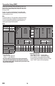
FUNCTION LIST
DX7G2, DX8G2, DX9, DX18, DX20
Timer
Mode Count Down
Time 4:00
Start Throttle Out
Over 25%
One Time Inhibit
SYSTEM SETUP
Model Type HELI
Swash Type Normal
F-Mode Setup
Switch 1 Switch B
Switch 2 Inhibit
Hold Switch Switch H
0
1
Channel Assign
Channel Input Confi g
1 Throttle
2 Aileron
3 Elevator
4 Rudder
5 Gear Switch B
6 Collective
7 AUX 2 Switch I
Frame Rate
11ms
DSMX