
User's Manual
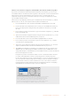
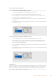
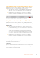
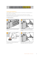

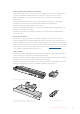
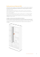

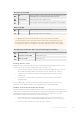
Table Of Contents
- Getting Started
- Connecting Videohub to a Network
- Smart Videohub Control Panel
- Videohub Hardware Control Panels
- Introducing Videohub Hardware Control Panels
- GPI and Tally Interface
- Connecting USB to Configure the Control Panel
- Plugging into an Ethernet Network
- Control Panel Button Diagnostics
- Updating the Software in your Videohub Controller
- About Routing Levels
- How to Select Sources and Destinations
- Using Videohub Smart Control Pro as a Cut-Bus Controller
- Using Videohub Smart Control Pro as an XY Controller
- Labeling Pushbuttons
- Universal Videohub Routers
- 3G-SDI Videohub Routers
- Videohub Router Monitoring
- Blackmagic Videohub Software
- Developer Information
- Help
- Regulatory Notices
- Safety Information
- Warranty
- English
- 日本語
- Français
- Deutsch
- Español
- 中文
- 한국어
- Русский
- Italiano
- Português
- Türkçe
- Developer Information
- はじめに
- Videohubをネットワークに接続
- Smart Videohubコントロールパネル
- Videohubハードウェアコントロールパネル
- Universal Videohubルーター
- 3G-SDI Videohub Routers
- Videohubルーターのモニタリング
- Blackmagic Videohubソフトウェア
- ヘルプ
- 規制に関する警告
- 安全情報
- 保証
- Mise en route
- Connecter le Videohub au réseau
- Panneaux de contrôle Smart Videohub
- Panneaux de contrôle matériels Videohub
- Panneaux de contrôle matériels Videohub
- GPI and Tally Interface
- Configuration du panneau de contrôle par USB
- Connexion au réseau Ethernet
- État des boutons sur le panneau de contrôle
- Mise à jour du logiciel Videohub Controller
- Niveaux de routage
- Sélectionner les sources et les destinations
- Utilisation du Videohub Smart Control Pro comme contrôleur Cut-Bus
- Utilisation du Videohub Smart Control Pro comme contrôleur XY
- Personnalisation des boutons
- Grilles de commutation Universal Videohub
- Grilles de commutation Videohub 3G-SDI
- Monitoring de la grille de commutation Videohub
- Logiciel Blackmagic Videohub
- Installation du logiciel Blackmagic Videohub
- Blackmagic Videohub Setup
- Blackmagic Videohub Control
- Configuration du Blackmagic Videohub Hardware Panel
- Configuration du Videohub Master Control Pro
- Configuration du Videohub Smart Control Pro
- Contrôle du Blackmagic MultiView 16 avec le logiciel Videohub
- Remplacer un ventilateur sur l’Universal Videohub
- Avis règlementaires
- Informations de sécurité
- Garantie
- Erste Schritte
- Anschluss einer Videohub an ein Netzwerk
- Smart Videohub Bedienpanel
- Videohub Hardware-Steuerpanels
- Neue Videohub Hardware-Steuerpanels
- GPI and Tally Interface
- Konfiguration des Steuerpanels per USB
- Anschluss an ein Ethernet-Netzwerk
- Testen der Steuertasten
- Aktualisieren der Software Ihres Videohub Controllers
- Über Steuerungsebenen
- Auswählen von Quellen und Zielen
- Verwendung des Videohub Smart Control Pro als Cut-Bus-Controller
- Verwendung des Videohub Smart Control Pro als XY-Controller
- Beschriftung der Steuertasten
- Universal Videohub Kreuzschienen
- 3G-SDI Videohub Kreuzschienen
- Monitoring mit Videohub Kreuzschienen
- Blackmagic Videohub Software
- Hilfe
- Gesetzliche Vorschriften
- Sicherheitshinweise
- Garantie
- Primeros pasos
- Conectar dispositivos Videohub a una red informática
- Smart Videohub Control Panel
- Paneles de control Videohub
- Nuevos paneles de control Videohub
- Dispositivo GPI and Tally Interface
- Conexión mediante el puerto USB para configurar el panel de control
- Conexión a una red Ethernet
- Diagnóstico de los botones en el panel de control
- Actualización del programa en el controlador Videohub
- Acerca de los niveles de distribución
- Cómo seleccionar fuentes y destinos
- Uso del panel Videohub Smart Control Pro para realizar cortes directos
- Uso del panel Videohub Smart Control Pro para realizar cambios XY
- Identificar botones
- Matrices de conmutación Universal Videohub
- Matrices Videohub SDI 3G
- Monitorización de las matrices Videohub
- Software Blackmagic Videohub
- Instalación de las aplicaciones Blackmagic Videohub
- Ejecute la aplicación Blackmagic Videohub Setup.
- Blackmagic Videohub Control
- Configuración del panel de control Videohub
- Configuración del panel Videohub Master Control Pro
- Configuración del panel Videohub Smart Control Pro
- Control del monitor Blackmagic MultiView 16 mediante Videohub Software
- Ayuda
- Normativas
- Información de seguridad
- Garantía
- 入门
- 将Videohub连接到网络
- Smart Videohub控制面板
- Videohub硬件控制面板
- Universal Videohub矩阵
- 3G-SDI Videohub矩阵
- Videohub矩阵监看
- Blackmagic Videohub软件
- 帮助
- 监管告知
- 安全信息
- 保修
- 시작하기
- Videohub를 네트워크에 연결하기
- Smart Videohub Control Panel
- Videohub 하드웨어 컨트롤 패널
- Universal Videohub 라우터
- 3G-SDI Videohub 라우터
- Videohub 라우터 모니터링하기
- Blackmagic Videohub 소프트웨어
- 도움말
- 규제 사항
- 안전 정보
- 보증
- Подготовка к работе
- Подключение коммутатора Videohub к компьютерной сети
- Панель управления на моделях Smart Videohub
- Аппаратные панели Videohub
- Обзор аппаратных панелей Videohub
- GPI and Tally Interface
- Подключение через USB для настройки панели управления
- Подключение к сети Ethernet
- Тестовая проверка кнопок на панели управления
- Обновление ПО на панели управления Videohub
- Уровневая организация маршрутизации
- Как выбирать источники и приемники сигнала
- Использование панели Videohub Smart Control Pro для управления прямым переключением
- Использование панели Videohub Smart Control Pro для управления переключением в два шага
- Добавление ярлыков на кнопки
- Коммутаторы Universal Videohub
- Коммутаторы Videohub с поддержкой 3G-SDI
- Мониторинг сигнала с коммутаторов Videohub
- ПО Blackmagic Videohub
- Помощь
- Соблюдение нормативных требований
- Правила безопасности
- Гарантия
- Operazioni preliminari
- Connettere Videohub a una rete
- Pannello di controllo di Smart Videohub
- Pannelli di controllo Videohub
- Introduzione
- GPI and Tally Interface
- Collegare il pannello di controllo al computer tramite USB
- Connessione a una rete ethernet
- Interpretare il colore dei pulsanti
- Aggiornare il software interno del pannello di controllo
- Livelli di routing
- Selezionare sorgenti e destinazioni
- Utilizzare Videohub Smart Control Pro come selettore diretto
- Utilizzare Videohub Smart Control Pro come selettore XY
- Inserire un’etichetta nei pulsanti
- Le matrici Universal Videohub
- Matrici Videohub 3G-SDI
- Monitorare i percorsi di routing
- Il software Blackmagic Videohub
- Assistenza
- Normative
- Sicurezza
- Garanzia
- Instruções Preliminares
- Conectando o Videohub a uma Rede
- Smart Videohub Control Panel
- Painéis de Controle Videohub Físicos
- Apresentando os Painéis de Controle Videohub Físicos
- GPI and Tally Interface
- Conectando USB para Ajustar Painel de Controle
- Conexão a uma Rede Ethernet
- Diagnóstico dos Botões do Painel de Controle
- Atualizando o Software no seu Controlador Videohub
- Sobre Níveis de Roteamento
- Como Selecionar Origens e Destinos
- Usando Videohub Smart Control Pro como um Controlador de Barramento de Cortes
- Usando Videohub Smart Control Pro como um Controlador XY
- Rotulando Botões
- Roteadores Universal Videohub
- Roteadores Videohub3G-SDI
- Monitoramento de Roteador Videohub
- Blackmagic Videohub Software
- Informações para Desenvolvedores
- Ajuda
- Informações Regulatórias
- Informações de Segurança
- Garantia
- Başlarken
- Videohub’un bir Ağa Bağlanması
- Smart Videohub Kontrol Paneli
- Videohub Donanım Kontrol Panelleri
- Videohub Donanım Kontrol Panelleri ile Tanışın
- GPI ve Tally Arayüzü
- Kontrol Paneli Yapılandırmak için USB’nin Bağlanması
- Bir Ethernet Ağına Bağlanma
- Kontrol Panel Buton Sistem Kontrolü
- Videohub Kontrol Cihazı Yazılımının Güncellenmesi
- Yönlendirme Seviyeleri Hakkında
- Kaynakların ve Hedeflerin Seçilmesi
- Videohub Smart Control Pro’yu Bir Cut-Bus Kontrol Cihazı olarak Kullanma
- Videohub Smart Control Pro’yu Bir XY Kontrol Cihazı olarak Kullanma
- Tuşların Etiketlenmesi
- Universal Videohub Yönlendiricileri
- 3G-SDI Videohub Yönlendiricileri
- Videohub Yönlendirici Görüntüleme
- Blackmagic Videohub Yazılımı
- Yardım
- Mevzuata İlişkin Bildirimler
- Safety Information
- Garanti

1 Hold the crosspoint card in a vertical orientation by its two levers. The BNC, Ethernet
and other ports should be towards the bottom end of the card.
2 Gently insert the card into its slot, ensuring the top and bottom edges follow the
black guides.
3 Firmly push both levers flat to fully engage the multi-pin connectors with the
motherboard. Mating pins ensure that the card precisely engages with the motherboard
without damaging the multi-pin connectors.
4 Use a number 01 size Pozidriv screwdriver to secure the two levers on the
crosspoint card.
It is common to install a second crosspoint card for failover redundancy and we recommend
doing this. If two crosspoint cards are installed, all video routes and port labels will be safely
retained even if one card becomes faulty and has to be replaced. To remove the blanking plate
from the right crosspoint card slot, you will need to use a number 02 size Pozidriv screwdriver.
MAIN POWER
+12V 800W
MAIN POWER
+12V
150W 150W 150W
ALARM
POWER OVERLOAD
ALARM
REF IN
RS-422
CONTROL
ETHERNET
USB DIAGNOSTIC
POWER OVERLOAD
ALARM
REF IN
RS-422
CONTROL
ETHERNET
USB DIAGNOSTIC
2
3
4
5
6
7
1
1 Status LED lights
2 Reference In
3 RS-422 router control
4 USB 2.0
5 Ethernet router control
6 Alarm GPI
7 Handle
Universal Videohub Status LEDs
The status LEDs marked ‘alarm’, ‘power overload’ and ‘ref in’ provide you with an indication of
the current state of the Blackmagic Universal Videohub 288 Crosspoint. The following
LED conditions provide specific information about the status of the unit.
Red ‘alarm’ LED
Off No error. Normal operation.
On Error condition. Other error. Telnet into device to get error code.
1
1 flash Error condition. Fan failure.
3
3 flashes Error condition. No redundant power supply.
29Universal Videohub Routers