
User's Manual
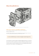
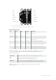
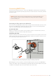
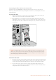

The rear view of the adapter’s connector housing.
Refer to the wire configuration table for a description of each pin
Wire Configuration Table
Pins Signal Color Direction Description
1, 2, 3, 4 Batt Red To URSA 12 V to 20 V
5, 6, 9, 10 GND Black – –
7 Monitor0 Blue To URSA Analog battery level or open drain data
line (20 V max)
8 Monitor1 Green To URSA Open drain clock line (3.4 V max)
12 +12 V out Orange From URSA 12 V regulated output 1.5 A max (18 W)
11 EnableN White To URSA Connect to GND to enable +12 V out.
Leave floating if +12 V out is not required.
Each Batt and GND pin supports 3 amps. Make sure all Batt and GND pins are connected.
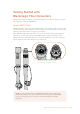
Tomonitor the battery status using Anton Bauer, IDX, or Blueshape plates, follow the
connection table below:
Anton Bauer Connect the blue/white striped wire to the housing blue wire at pin 7.
IDX
Connect the green wire to the housing green wire at pin 8,
and the grey wire to the housing blue wire at pin 7.
Blueshape
Connect the blue wire labelled "SMBC " to the housing green wire at pin 8.
Connect the brown wire labelled "SMBD" to the housing blue wire at pin 7.
Secure any unused wires by cutting them as close as possible to the rear of the
adapterconnector.
Batt 2
Batt 4
GND 6
Monitor 1 8
GND 10
+12V Out 12
1 Batt
3 Batt
5 GND
7 Monitor0
9 GND
11 EnableN
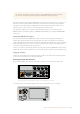
135Mounting Batteries