Installation and Operation Manual Blackmagic URSA Broadcast Includes Blackmagic Camera Fiber Converter, Studio Fiber Converter, Blackmagic URSA Viewfinder, URSA Studio Viewfinder and URSA Mini Shoulder Mount Kit February 2018
English Welcome Thank you for purchasing Blackmagic URSA Broadcast! Since we released our first digital film camera a few years ago we have been privileged to have received some of the best guidance and feedback we have ever had for a new product! We all grew up admiring the work of the world’s leading cinematographers and DOPs and it’s been an honor to spend hours in conversations with these legendary experts on the features we need to add to our cameras.
Contents Blackmagic URSA Broadcast Getting Started 6 Touchscreen Controls 50 Attaching a Lens 6 Touchscreen 50 Powering your Camera 7 Touchscreen Features 50 Using Servo Zoom Lenses 10 Settings 70 Storage Media 17 Dashboard 70 CFast Cards 17 Record Settings 70 SD Cards 20 File Naming Convention 75 Preparing Media for Recording 23 Monitor Settings 76 Preparing Media on Blackmagic URSA Broadcast 24 Audio Settings 83 Preparing Media on Mac 26 Presets 96
Mounting Batteries 133 Camera Unit Connections 156 Mounting V-mount or Gold Mount Batteries 133 Camera Power Connection 156 Using your own Battery Plate 134 PTZ Interface 156 Talkback Connection 157 Blackmagic Fiber Converters 136 Tracker Interface 158 Getting Started with Blackmagic Fiber Converters 137 DC Connection 158 About SMPTE Fiber 137 Reference Output and Operation 159 Connecting SMPTE Fiber 139 Why Connections on the Front? 144 Plugging in Camera SDI 14
URSA Mini SSD Recorder 179 The Fairlight Page 206 Mounting and connecting URSA Mini SSD Recorder 180 The Audio Timeline 206 Using URSA Mini SSD Recorder 182 The Mixer 207 Updating URSA Mini SSD Recorder’s internal software 183 Using the Equalizer to Enhance your Audio 208 What is a Bus? 207 Mastering your Edit 210 Understanding Studio Camera Control 184 Working with RAW files 211 Using Camera Control 185 Blackmagic Camera Setup Utility 214 DaVinci Resolve Primary Color
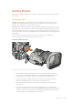
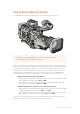
Getting Started Getting started with URSA Broadcast is always as simple as mounting a lens and powering your camera. Attaching a Lens URSA Broadcast is shipped with a B4 mount for attaching B4 mount lenses. These lenses typically have a built in handle and strap that lets you hold the camera securely on your shoulder, plus control the zoom rocker and iris controls.
For information on the types of B4 lenses and how to use them with your camera, refer to the 'Using Servo Zoom Lenses' section in this manual. NOTE When no lens is attached to the camera, the optical element of URSA Broadcast's B4 mount is exposed to dust and other debris. Ensure that you keep the dust cap on whenever possible. Many B4 lenses can be quite long due to their extreme zoom range. When using URSA Broadcast with B4 lenses, your camera's center of gravity will move forward.
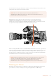
AUDIO 1 IN IN IO D U A 2 To plug in external power: 1 Connect the AC to 12V DC adapter plug to your mains power socket. 2 Connect the AC to 12V DC adapter’s 4 pin XLR connector to the 12-20V DC power connector on the camera. If you have both external and battery power connected, only external power will be used. If you remove external power while a charged battery is connected, your camera will switch to battery power without interruption.
SD CFAST URSA Broadcast also features a redundant power switch, which allows the camera to be turned MIC on and off by holding down the 'rec' and 'forward skip' buttons on the inside control panel. LINE While you wouldn't normally power your cameraAES using this method, it is provided as a helpful alternative if the power switch along the top edge is obscured, for example when mounted on a custom rig.
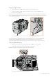
Using Servo Zoom Lenses Your URSA Broadcast camera natively supports servo driven B4 broadcast lenses. LENS TIP Using the optional URSA Mini Pro PL mount fitted, URSA Broadcast is also compatible with servo driven PL cine lenses. B4 broadcast lenses offer several features that aren’t typically present in still photography and cinema lenses. In addition to the ability to hold focus through a large zoom range, these lenses are distinguished by handgrip controls and servo driven iris and zoom functions.
B4 lens controls Iris On the top of most B4 handgrips, you’ll find an 'auto/manual' or 'A/M' switch, and a 'push auto' or 'iris' switch. These control the your lenses’ aperture ring. Auto Set this switch to ‘auto’ or ‘a’ to adjust your lens aperture via your URSA Broadcast or an ATEM switcher. You can adjust lens aperture from URSA Broadcast using the iris wheel, internal control panel buttons, touchscreen controls, or iris based auto exposure modes.
Zoom On the underside of most B4 handgrips, you’ll find a ‘zoom’ switch that can be set to ’servo’ or ‘manual.’ This controls zoom behavior. Servo Set this switch to ‘servo’ or ’s’ to enable servo zoom control. In this mode, the rocker switch on your handset can be used to zoom your lens in and out, as well as any other zoom related controls, such as zoom speed and quickzoom.
Focus Some B4 lenses also have focus servo controls. If this control is present on your lens, you’ll see a ‘focus’ switch on the underside of the handgrip with two settings, ‘servo’ and ‘manual.’ Servo Set this switch to ‘servo’ or ’s’ to enable servo focus control. In this mode, your lens can accept focus commands from URSA Broadcast or an ATEM switcher via the 12 pin hirose connector. Manual S FOCUS M S ZOOM M Set this switch to ‘manual’ to use the focus ring on the lens barrel to control focus.
Setting the Back Focus on B4 Lenses One of the huge advantages of B4 lenses is that they are designed to be ‘parfocal’ which means they hold focus all the way through the zoom range. This means you can zoom in, get focus on an object and then when you zoom out it will remain in focus. The back focus ring is typically located at the rear of the lens, close to the mount Back focus is critical in ensuring that your HD or 4K B4 lenses retain focus right through the zoom range.
Using Box Lenses Large studio box lenses like Fujinon’s UA series and Canon’s CJ series lenses can also be used with URSA Broadcast or URSA Mini Pro’s B4 mount. These types of box lenses allow horizontal and vertical image stabilization on studio style 27x lenses, as well as extreme zoom ranges with 80x, 86x, 90x and even 107x magnification which are incredible for broadcasting sports and outdoor events.
PL Servo Zoom Lenses PL zoom lenses used for motion pictures can also be used with your URSA Broadcast. These lenses are designed for super 35mm which is a larger format compared to 2/3" sensors, so the image from the lens will have a narrower field of view to when it is used on a Super 35mm sensor camera. This can be effective as it decreases you field of view, so you get the effect of zooming in even tighter.
Storage Media Ursa Broadcast uses CFast 2.0 cards or fast UHS-II and UHS-I SD cards to record Ultra HD, 2K or HD video. CFast Cards CFast 2.0 cards are capable of supporting very high data rates, so are perfect for recording HD and 4K video at high frame rates. Refer to the record duration table in the ‘recording’ section for details on the maximum frame rates that can be recorded in each format. NOTE While CFast 2.
Choosing a CFast 2.0 Card When working with high data rate video it’s important to carefully check the CFast card you would like to use. This is because CFast 2.0 cards have different read and write speeds. Some cards can record sustained RAW video, and some are suited to compressed recording using ProRes and compressed RAW formats. The tables below identify the CFast cards recommended for use when shooting with Blackmagic URSA Broadcast.
The following CFast 2.0 cards are recommended for 2160p ProRes 422 HQ up to 60 fps. Brand Card Name Storage Angelbird AVpro CF 160GB Angelbird AVpro CF 240GB KomputerBay 3400x CFast 2.0 Card 64GB KomputerBay 3400x CFast 2.0 Card 128GB KomputerBay 3600x CFast 2.0 Card 64GB Lexar Professional 3500x 64GB Lexar Professional 3500x 128GB Lexar Professional 3500x 256GB Lexar Professional 3600x 128GB Lexar Professional 3600x 256GB SanDisk Extreme Pro.
SD Cards In addition to CFast 2.0 cards, Blackmagic URSA Broadcast can record on high speed UHS-I and UHS-II type SD cards. Using high end SDXC UHS-II cards, you can even record ProRes HQ footage in 2160p for Ultra HD content! With SD cards, you can use more affordable storage media when shooting compressed video formats in HD. SDXC and SDHC are a very common media storage format for consumer still and video cameras.
If you want to, you can format your cards using a Mac or Windows computer. When using your media on Mac OS, you can use HFS+ which is the Mac disk format. If you are using Windows then you should use exFAT format, which is the Windows disk format that Mac computers can also read. The tables below identify the SD cards recommended for use when shooting with Blackmagic URSA Broadcast. It’s worth regularly checking the latest version of this manual for more up to date information.
Brand Card Name Storage SanDisk Extreme Pro UHS-I 95MB/s SDXC 128GB SanDisk Extreme Pro UHS-II 280MB/s SDXC 64GB Sony SF-G64 300MB/s UHS-II 64GB Sony SF-G128 300MB/s UHS-II 128GB Toshiba Exercia Pro UHS-II 270MB/s SDXC 64GB Toshiba Exercia Pro UHS-II 270MB/s SDXC 128GB Toshiba Exercia Pro UHS-II 270MB/s SDXC 256GB Transcend Ultimate UHS-II 180MB/s SDXC 64GB The following SD cards are recommended for recording up to 1080p60 ProRes HQ Brand Card Name Storage Angelbird AV Pro 300
Locking and Unlocking SD Cards SD cards can be write protected, or 'locked', to prevent data from being overwritten. When inserting an SD card, make sure the card is not write protected. Write protection is disabled by moving the plastic switch on the left side of the card to the position closest to the connectors. After recording, you can then write protect the card by sliding the switch back down to the bottom position.
NOTE Before formatting your media, it's important to make sure the media storage switch has been set correctly to either SD card or CFast card. Always check the settings carefully before formatting. Preparing Media on Blackmagic URSA Broadcast 1 Tap either storage indicator at the bottom of the LCD touchscreen to enter the storage manager. 2 Tap 'Format Card 1' or 'Format Card 2' to format the CFast card in slot 1 or 2, respectively.
Check that you have selected the correct card before formatting 6 You will be notified when the format is complete. 7 Tap 'ok' to return to the storage manager. 8 Tap 'exit' to leave the storage manager. When formatting CFast or SD cards using the storage manager, your URSA Broadcast will use the Camera ID from the slate and reel number to name the card. Your camera automatically increments reel numbers each time you format.
Preparing Media on Mac Use the Disk Utility application included with Mac OS to format your card in the HFS+ or exFAT formats. Remember to back up anything important from your CFast or SD card as all data will be lost when it is formatted. 1 Connect the CFast or SD card to your computer using a CFast 2.0 or SD reader/ writer or CFast drive, and dismiss any message offering to use your card for Time Machine backups. 2 Go to applications/utilities and launch Disk Utility.
Use the ‘format’ dialog box feature in Windows to format your CFast or SD card in the exFAT format NOTE If your recordings are dropping frames, check that your card is on our list of recommended media for the codec and frame size you are using. For lower data rates try lowering your frame rate, resolution, or try a compressed codec such as ProRes. Check the Blackmagic Design website for the latest information at www.blackmagicdesign.
Recording Recording Clips B4 broadcast lenses typically have a record button positioned on the lens handle where your thumb would be when shooting from the shoulder. Simply press the record button on the handle to start recording. Press again to stop recording. Your camera has record buttons built into the camera itself. A record button is located on the inside control panel, and on the forward control panel for convenient access when shooting from the shoulder.
Maximum Sensor Frame Rates The tables below contain available codecs, resolutions and their maxiumum sensor frame rates.
Trigger Record Your URSA Broadcast automatically sends a signal via the SDI outputs that will trigger recording when connected to equipment that supports the SDI trigger record feature, such as Blackmagic Video Assist. This means when you press record on your camera, your external SDI equipment will also start recording, and will stop recording when you press record again.
HD Progressive CFast Card Frame Rate DNxHD 220x DNxHD 145" ProRes 444 XQ ProRes 444 ProRes 422 HQ ProRes 422 ProRes 422 LT ProRes 422 Proxy Duration Duration Duration Duration Duration Duration Duration Duration 23.98 190 mins 285 mins 84 mins 127 mins 189 mins 283 mins 403 mins 877 mins 24 189 mins 285 mins 84 mins 127 mins 189 mins 283 mins 403 mins 877 mins 25 182 mins 274 mins 81 mins 122 mins 182 mins 271 mins 387 mins 843 mins 29.
Playback Playing Back Clips Once you have recorded your video, you can use the transport control buttons to play back your clips. Press the ‘play’ button once for instant playback and you’ll see your recorded video on URSA Broadcast's LCD touchscreen. Your clips can also be viewed on any display connected to your URSA Broadcast's SDI outputs.
Operating URSA Broadcast Industry standard BNC connectors are located on the right and rear panel of your URSA Broadcast for SDI connections. There are also two separate LANC inputs, one for the optional URSA side handle and one at the rear of the camera for an external LANC controller. XLR inputs are on the top panel behind the mounting points for professional balanced analog audio and AES digital audio.
Left Side URSA Broadcast's left side panel lets you insert CFast cards, access the control panel and change settings. The USB-C port is located just above the CFast slots so you can easily plug into a computer when updating your URSA Broadcast's internal software. Left Side Controls The left side panel features additional controls for easy access to all of your camera's essential functions.
10 Storage Media Selection Switch Use this switch to choose between CFast and SD storage media. 11 USB Port USB-C port for updating internal software. See the section 'Blackmagic Camera Setup Utility' for more information.
15 HD Monitoring Output 3G-SDI connector for down converted 1080HD output. Use with Blackmagic URSA Viewfinder or external monitors. Refer to the 'camera video output' and ‘Blackmagic URSA Viewfinder’ sections for more information. 16 +12V Power Output 4 pin XLR connector for powering Blackmagic URSA Viewfinder, Blackmagic URSA Studio Viewfinder or external monitors and accessories. Refer to the ‘Blackmagic URSA Viewfinder’ and ‘Blackmagic URSA Studio Viewfinder’ sections for more information.
22 12G-SDI In The 12G-SDI input is used for connecting to a switcher or external recorder. This means if you’re using URSA Broadcast in a live broadcast, you can plug in the switcher’s program output and monitor it during the shoot, or check playback from an external recorder. Press and hold the program button to see your program feed. For more information, refer to the 'Ergonomic Control Panel' section in this manual.
27 XLR Audio In Use the balanced XLR inputs to plug in external analog audio from professional equipment such as audio mixers, PA systems or external microphones. The XLR connectors supply 48V phantom power so you can use microphones that aren’t self powered. To enable phantom power select ‘inputs’ on the ‘audio input’ setting, plus ‘mic low’ or ‘mic high’ on the audio ‘input levels’ settings. Scroll the menu to reveal the ‘phantom power’ setting and select ‘on’. To disable phantom power, select ‘off’.
URSA Broadcast Controls Blackmagic URSA Broadcast has control panels on the chassis, outside and inside of the foldout touchscreen monitor to give you quick, easy access to all of its essential functions as well as powerful monitoring tools. These panels are designed to be close to hand whether shooting from a tripod, handheld or with the shoulder mount kit.
2 ND Filters Your URSA Broadcast has three internal neutral density filters. Together with a clear filter, the available settings are ‘2,’ ‘4’ and ‘6’ stops. These filters allow you to reduce the amount of light reaching your URSA Broadcast's sensor by a preset number of exposure 'stops'. By reducing the exposure, you can continue shooting at wide apertures in bright conditions such as outdoors on sunny days. To adjust your neutral density setting, rotate the wheel upwards or downwards.
4 Menu Wheel When 'status text' is turned on for your camera's front SDI output, you can use the menu wheel to navigate many of the head up display features usually accessed via the LCD touchscreen. Simply press the menu wheel as you would a button to access your URSA Broadcast's head up display on an external monitor such as Blackmagic SmartView, Video Assist or URSA Viewfinder.
7 Auto White Balance Pressing this button will reveal a white ‘auto white balance’ box in the center of the LCD for five seconds. This box will also appear on any SDI output that has ‘status text’ enabled in the menu settings. The white box indicates the specific area of your image where the white balance will be calculated from, so your gray card should be positioned within this box.
10 Monitor Speaker The small speaker built into the outside control panel lets you listen to the audio while shooting. It is located where your ear would normally be when shooting with the camera on your shoulder. To adjust the volume of the speaker, simply rotate the settings wheel as described in the 'URSA Broadcast Controls' section. 11 Monitor Channel Select Your URSA Broadcast currently supports two channels of audio.
Battery indicator If your URSA Broadcast is running on battery power, this indicator displays remaining battery life in 25% increments. Each of the battery indicator’s four bars corresponds to 25% battery life remaining. When your battery drops below 20% charge, the colour of the status LED, near the record button begins to flash. It will alternate slowly between red and orange during recording and alternate between white and orange during standby mode.
ON OFF 14 Status LCD Controls ON OFF URSA Broadcast status LCD controls Still Press this button to capture a still image as a single uncompressed DNG frame. Image files will be saved to the 'stills' folder in the root directory of the media you are currently recording to. These will follow the file naming convention for video clips but the filename will have an ‘S001’ representing the ‘still number’ as the last four digits of the filename.
15 Control and Playback Buttons ON OFF URSA Broadcast control and playback buttons Iris The 'iris' button activates the automatic aperture setting on compatible lenses. When using video dynamic range settings, a single press of the iris button will set an average exposure based on the highlights or shadows in your shot. When using film dynamic range settings, pressing the iris button sets your exposure to the brightest highlight in your shot.
16 Audio Level Adjustment Knobs ON OFF URSA Broadcast audio adjustment knobs Use the built in adjustment knobs to set the recording levels for audio channels 1 and 2. Turn each knob clockwise or counterclockwise to increase or decrease the recording level for each channel of audio. Monitor the corresponding on screen audio meters as you adjust each knob so you can see the best level to set it to.
NOTE It is standard practice to plug in your XLR cable before switching phantom power on. It is also important to switch phantom power to ‘off' when you no longer have a phantom powered microphone connected. Connecting devices that don’t have phantom power protection built into their AES XLR outputs whilst still sending phantom power from the camera’s XLR audio inputs may damage your equipment. Always ensure that the +48V switch is turned ‘off’ when you disconnect your microphone.
Menu Press the ‘menu’ button to open the dashboard. Refer to the ‘settings’ section for more information about the dashboard feature and how to adjust settings. Record Press any of the record buttons marked REC to start and stop recording. Refer to the ‘recording’ section for more information. Playback Control Buttons The playback buttons let you start and stop playback, plus skip to the next or previous clip.
Touchscreen Controls Touchscreen Your Blackmagic URSA Broadcast's fold out LCD touchscreen pivots for shooting high and low angles. Buttons on the outside of the LCD panel let you control your URSA Broadcast when mounted on your shoulder using the URSA Viewfinder and the LCD closed. Touchscreen Features The LCD touchscreen features a touch and gesture based interface that is specifically designed for fast and intuitive user operation.
Tap the 'zebra' icon while accessing 'LCD monitor options' to access your URSA Broadcast's zebra settings To toggle zebra for the LCD touchscreen, tap the switch icon in the bottom left of the screen while in the 'zebra' tab. Set the exposure level that zebra appears at by dragging the slider left and right, or tapping the arrow buttons next to the zebra level percentage. Zebra level is adjustable in five percent increments between 75 and 100 percent exposure.
Frame Guides The ‘frame guide’ setting toggles the appearance of frame guides on the LCD touchscreen. You can also choose from seven frame guide options for all outputs on your URSA Broadcast. Frame guides include aspect ratios for various cinema, television and online standards.
TIP You can change the opacity of frame guide overlays. For more information see the ‘monitor settings’ section of this manual. NOTE For information on enabling frame guides on your camera’s front and main SDI outputs, see the ‘monitor settings’ section in this manual. Grids The ‘grids’ setting toggles the appearance of a rule of thirds grid, crosshair or center dot on the LCD touchscreen, as well as setting the overlay that will be visible on all URSA Broadcast's outputs.
The rule of thirds grid automatically scales to any on screen frame guides Thirds The ‘thirds’ setting displays a grid with two vertical and horizontal lines placed in each third of the image. Thirds are an extremely powerful tool to help compose your shots. For example, the human eye typically looks for action near the points where the lines intersect, so it’s helpful to frame key points of interest in these zones.
Safe area guides can also be used to assist with framing your shot where you know that the shot will be stabilised in post production, which can crop the edges of the image. They can also be used to indicate a specific crop. For example by setting it to 50% whilst recording at Ultra HD 3840x2160 you can see what a 1920x1080 crop of the frame would look like. The safe area guides also scale to your frame guides, so they will adjust to indicate the chosen percentage of your target frame.
ND Filter indicator Adjusting your URSA Broadcast's ND filter will display the ND filter indicator in the top left of the LCD touchscreen and any SDI outputs set to show status text. This indicator will be shown for four seconds and use the format you've selected in your URSA Broadcast's setup menu. Adjusting your URSA Broadcast's ND filter setting will reveal the ND filter indicator NOTE You can adjust the terminology used by the ND filter indicator to reflect the conventions you're used to.
Sensor frame rate The sensor frame rate sets how many actual frames from the sensor are recorded every second. This frame rate will affect how fast or slow your video will play back at your set project frame rate. With 'off speed frame rate' enabled, tap the arrows on either side of the sensor frame rate or move the slider to make adjustments y default, your URSA Broadcast's project and sensor frame rates are matched for a B natural playback speed.
URSA Broadcast's shutter indicator. Tap this to access shutter settings hutter speed defines the level of motion blur in your video, and can be used to compensate S for varying light conditions. The shutter speed setting for natural motion blur, and the settings available, depend on the frame rate you are using. For example, when shooting at 30p, a 1/60 of a second shutter speed is is the equivalent of a 180 degree shutter angle, a very common setting for film projects.
If you are shooting outside, or using flicker free lights, you can also manually select a shutter speed by double tapping the current shutter indicator at the bottom left of your screen. This will bring up a keypad which you can use to set any shutter speed for your chosen frame rate. Use the manual shutter keypad to enter your shutter speed of choice when shooting outdoors or under flicker free lights Your URSA Broadcast has three shutter based auto exposure modes.
Iris The ‘Iris’ indicator displays your current lens aperture. By tapping this indicator, you can change the aperture of compatible lenses and configure iris based auto exposure modes. Your URSA Broadcast's iris indicator. Tap this to access iris settings NOTE To adjust your iris from the LCD touchscreen, your URSA Broadcast must be fitted with a lens that supports changing aperture via the camera.
When an auto exposure mode that effects the iris is enabled, a small “A” will appear next to the iris indicator at the top of your URSA Broadcast touchscreen. TIP Automatic exposure works smoothly with compatible B4 or PL lenses which are designed for video or film production. EF lenses may produce noticeable ‘steps’ in exposure when changing aperture. For this reason, we recommend using only ‘shutter’ auto exposure mode if shooting with EF lenses.
Your URSA Broadcast's gain indicator. Tap the indicator to access gain settings º While in the 'gain' menu, your URSA Broadcast's gain settings appear along the bottom of the LCD touchscreen Depending on your situation, you may choose a lower or higher gain setting. For example, in low light conditions +12dB can be suitable but may introduce some visible noise. In bright conditions -6dB can provide richer colors.
o further dial in your image, you can adjust the ‘tint.’ This adjusts the mix of green and magenta T in your image. For example, adding some magenta can compensate for the green cast of many fluorescent lights. Many of your URSA Broadcast's white balance presets include some tint. Tapping the white balance and tint indicator on your URSA Broadcast gives you access to five presets, as well as a white balance indicator and slider on the left, and a tint indicator on the right.
Power Your URSA Broadcast's power status is displayed in the top right of the LCD screen. There are four possible indicators: Your URSA Broadcast's power indicator is at the top right of the LCD touchscreen. While using battery power, tapping this toggles between 'voltage' and 'percentage' displays AC Displayed when your URSA Broadcast is plugged into mains power.
The left edge of the histogram displays shadows, or blacks, and the far right displays highlights, or whites. When you close or open the lens aperture, you’ll notice the information in the histogram moves to the left or right accordingly. You can use this to check 'clipping' in your image shadows and highlights. If the left and right of your edges of the histogram come to an abrupt stop rather than falling off gradually, you may be losing highlight or shadow detail.
NOTE You can set your URSA Broadcast to stop recording if dropped frames are detected to prevent a situation where you waste time shooting unusable footage if you don't notice the dropped frame indicator. See the 'record settings' section in this manual for more information. Recording Time Remaining At the bottom of your URSA Broadcast touchscreen, you’ll see the CFast card indicators.
You can format CFast cards from this menu. For more information on formatting CFast cards using URSA Broadcast, see the 'preparing media on Blackmagic URSA Broadcast' section of this manual. TIP Tapping the card name in the storage menu sets it as the active card. Your URSA Broadcast will fill this card first. Audio Meter The peak audio meters display audio levels for channels 1 and 2 when using the internal microphone, or via external audio when connected.
Double tap to zoom You can magnify any part of your URSA Broadcast's preview image by double tapping the LCD touchscreen. The area you tap will be magnified, and you can move around the image by dragging your finger around the LCD touchscreen. This is very helpful when checking focus. To return to standard magnification, simply double tap your camera’s touchscreen again. While zoomed in, an indicator in the top left of your LCD touchscreen will show which part of the image you are viewing.
When using the LCD touchscreen, tap ‘play’ once to start playback and again to pause. Use the forward and reverse buttons just as you would on a CD player. Tapping ‘forward’ once will move you to the next clip, while tapping ‘reverse’ once will move you back to the beginning of the current clip. Tapping ‘reverse’ twice will move to the beginning of the previous clip. Playback of clips can also be looped by activating the loop icon.
Settings Dashboard Pressing the ‘menu’ control button on your URSA Broadcast will bring up your camera's dashboard. This is a tabbed menu containing the settings not available from your URSA Broadcast's head up display. Settings are divided by function into ‘record,’ ‘monitor,’ ‘audio,’ ‘setup,’ ‘presets,’ and ‘LUTS’ tabs. Some tabs, such as ‘record,’ ‘monitor,’ and ‘setup’ contain multiple pages.
Codec and Quality The ‘codec and quality’ menu is split into two rows. The top row lets you choose between three codec families, CinemaDNG RAW, Apple ProRes and Avid DNxHD, while the bottom row offers quality options within those families. For example, the quality options available within the RAW codec family are ‘lossless’, ‘3:1’ and ‘4:1’. TIP The amount of video you can record on a CFast card, or SD card will increase when choosing codecs that utilize higher compression.
Dynamic Range Adjust the ‘dynamic range’ setting by tapping the dynamic range icons. Blackmagic URSA Broadcast has three dynamic range settings: Video The 'video' setting is similar to the REC 709 color standard for high definition video. This setting reduces dynamic range, but lets you work faster by recording directly to the compressed video formats in a color space suitable for direct delivery or minimal post processing.
Off Speed Recording By default, your URSA Broadcast's project and sensor frame rates are matched for a natural playback speed. However, by tapping the 'off speed recording' switch icon you can set your sensor frame rate independently. Off Speed Frame Rate With ‘off speed frame rate’ enabled, tap the arrows next to the ‘off speed frame rate’ indicator to set your URSA Broadcast's sensor frame rate. The sensor frame rate sets how many actual frames from the sensor are recorded every second.
Record Settings 3 The third page of the 'record' settings tab contains the following settings. Timelapse This setting activates the time lapse feature to automatically record a still frame at the following intervals: Frames 2 - 10 Seconds 1 - 10, 20, 30, 40, 50 Minutes 1 - 10 For example, you can set the camera to record a still frame every 10 frames, 5 seconds, 30 seconds, 5 minutes etc. The time lapse feature offers many creative options.
This setting is intended for live studio production where there is no time for post production and you want to output the image live to air. If you are doing extensive image manipulation and color correction in post production then we recommend leaving detail sharpening ‘off’. For this reason sharpening is not applied to RAW files that are intended for significant post processing.
Monitor Settings The ‘monitor’ tab lets you adjust status text, overlays, and other monitoring options for your URSA Broadcast's LCD touchscreen, front and main SDI outputs. Options are arranged by output between ‘LCD’, ‘front SDI’ and ‘main SDI’, as well as ‘all,’ which covers monitor settings that affect all outputs on your URSA Broadcast. Each of these menus has two pages of options, which you can cycle through by tapping the arrows at the edge of your camera’s touchscreen, or swiping left or right.
Display 3D LUT Your URSA Broadcast can apply 3D LUTs to any output to approximate the look of color graded footage. This is especially useful when shooting RAW footage, or with ‘film’ dynamic range in ProRes or DNxHR, as these produce an intentionally ‘flat’ low contrast image. If your URSA Broadcast has a 3D LUT active, use this setting to independently apply that LUT to your LCD touchscreen, front or main SDI output.
LCD Monitor Settings 2 The second page of your URSA Broadcast's 'LCD' monitor tab contains settings unique to your LCD touchscreen. Display Instead of a histogram and audio meters, your URSA Broadcast can display codec and resolution information at the left and right bottom edges of the LCD touchscreen.
Display Status Text For Cinematographer or Director Your URSA Broadcast's LCD touchscreen displays information such as ISO, white balance, and aperture that is useful to a camera operator or cinematographer setting up individual shots on that camera. URSA Broadcast's front and main SDI outputs, however, can also show information useful to a director or script supervisor who is keeping track of multiple shots or cameras.
SDI Output Both outputs allow you to choose between progressive and interlaced HD output, while your URSA Broadcast's main SDI output also has to option of progressive Ultra HD. The options available in this setting depend on your camera's resolution and frame rate settings. Progressive HD, or '1080p' is always available regardless of your recording resolution and frame rate, while interlaced HD, or '1080i' is available when your project frame rate is set to 50, 59.94 or 60.
Guide Opacity Tap the left or right arrows in the ‘guide opacity’ menu setting to choose the opacity of the areas blocked out by frame guides on your LCD touchscreen, front and main SDI outputs. The options are 25%, 50%, 75% and 100%. Focus Assist Your URSA Broadcast camera has two focus assist modes, ‘peak’ and ‘colored lines.
All Monitor Settings 2 The second page of your Ursa Broadcast's 'all' monitor tab contains the following options: Grids To set which combination of grids and crosshairs you want to display on your URSA Broadcast's LCD touchscreen, front and main SDI outputs, tap the ‘thirds,’ ‘crosshairs,’ or ‘center dot’ options in this setting. For more information, see the ‘grids’ guide in the ‘touchscreen features’ section earlier in this manual.
Audio Settings The ‘audio’ tab lets you adjust the audio input and monitoring settings on your URSA Broadcast. The settings are spread over two pages and divided between channels 1 and 2, while an upcoming software update will add two additional channels. You can map each audio channel to a different source, as well as adjusting various settings such as padding and low cut filters. These settings work together with the switches on your URSA Broadcast's internal control panel.
Recorded Channel 1/2 Level Use these sliders to adjust the recording levels of your chosen channel 1 and 2 sources. Audio meters are included with each slider to help you set the correct audio level. These levels will also update when you adjust the audio using the audio knobs on the ergonomic control panel. To achieve optimum audio quality, ensure your audio levels do not reach 0 dBFS.
Setup Settings The ‘setup’ tab contains your URSA Broadcast's identification settings, software version, function button settings and other camera settings not directly linked to recording or monitoring. This menu has four pages, which you can cycle through by tapping the arrows at the edge of the LCD touchscreen, or swiping left or right. Setup Settings Page 1 The first page of your URSA Broadcast's 'setup' tab contains the following settings.
NOTE The characteristics of individual light sources may still cause flicker even when using flicker free speeds. We recommend always performing a test shoot when not using continuous lights. Battery Display Your URSA Broadcast can change the way the battery level indicator displays the remaining charge. The two settings are ‘percentage’ and ‘voltage.
Setup Settings Page 2 The second page of your URSA Broadcast's 'setup' tab contains the following settings. ATEM Camera ID If you’re using URSA Broadcast with an ATEM Switcher and want your camera to receive tally signals from the switcher, you’ll need to set the camera number on your camera. This ensures the switcher sends the tally signal to the correct camera. The camera number can be set to a value of 1-99 by tapping the left or right buttons. The default setting is 1.
NOTE When you are setting your reference source for URSA Broadcast, you may experience a small dropout on your camera’s outputs when switching between your reference sources. This is because the camera is adjusting its referencing timing to match that of the external source. For this reason it is important not to change this setting during a production and only while setting up. Reference Timing These settings allow you to manually adjust the reference timing on a line or pixel basis.
To set these buttons, select a function button and then its behavior, a setting, and a parameter for that setting. 1 2 3 4 1 Button 2 Behavior 3 Setting 4 Parameter Function 1/2 Behaves as Once you have selected the function button you want to map, you can select a behaviour. The available options are: Preset When set to this behavior, pressing a function button will recall a combination of a setting and a parameter.
Setup Settings Page 4 The fourth page of your URSA Broadcast's 'setup' tab contains the following settings. Status LED Your URSA Broadcast has a small LED on the front panel that provides tally and status information. You can enable or disable it by tapping the ‘Status LED’ switch icon. The LED will provide the following status indicators: White The camera is powered on and in ‘standby’ mode. Red The camera is recording.
When selecting 'factory reset' you will be prompted to confirm your action Hardware ID The ‘Hardware ID’ indicator displays an 8 character identifier for your URSA Broadcast. This is unique to each camera. A longer, 32 character version of this ID is also included in the metadata for RAW and ProRes video. This can be useful for identifying which footage came from a particular camera if filenames are changed as the camera hardware ID remains constant.
Bluetooth® Bluetooth control allows you to control your camera wirelessly from portable devices. Using the ‘Blackmagic Camera Control App’ you can power the camera on or off, change settings, adjust metadata and trigger record remotely from an iPad. You can enable or disable Bluetooth by tapping the ‘Bluetooth’ switch icon in the ‘setup' menu. When Bluetooth is enabled, the camera can be detected by Bluetooth devices up to 30 feet away.
3 When you try to connect for the first time the Blackmagic Camera Control App will request a six digit code to pair with the camera. This code will be displayed on the camera’s LCD screen. Type this code into the iPad. 4 The information on the screen will confirm that your URSA Broadcast is now paired with your iPad.
5 If there is a problem pairing the camera to your iPad you will see the following error message: NOTE If you are not using Bluetooth to control your URSA Broadcast, it is a good idea to turn Bluetooth off for the purpose of security. Disconnect Current Device Use this setting to disconnect your URSA Broadcast from the iPad it is currently paired with. Clear Paired Devices Use this setting to clear the list of devices that your URSA Broadcast has been paired with.
Tap the slate icon in the lower right corner to access and update the slate URSA Broadcast uses Bluetooth LE to communicate with devices for wireless control. As this is the same type of protocol used in portable devices, it only uses a minimal amount of battery power. You can power off your URSA Broadcast by tapping 'power off' in the top right corner.
Presets The 'presets' tab lets you save and recall a complete collection of settings for your URSA Broadcast. This is very useful when one camera is used for multiple projects. For example, you may use your URSA Broadcast for a variety of different shoots, from documentaries to music videos, with very different settings between types of projects. Your URSA Broadcast's 'presets' function lets you save the setup for a particular project or type of shoot and come back to it quickly and easily when required.
Enter a name for your preset by tapping the 'add' icon in the preset tab and using the touch keyboard Once you have a preset saved, tap its name in the preset menu to select it. To load it tap the ‘load’ icon. Select a preset and tap the 'load' icon to load it. Selected presets will appear solid blue, while currently loaded presets have a blue line along the bottom of their icon You can update a preset by tapping the 'update' icon.
NOTE If your URSA Broadcast's preset slots are full, the import menu will not be available. You will need to delete an existing preset to make room. Exporting presets To export a preset to a CFast or SD card, select the preset you want to export by tapping it, and tap the ‘manage’ icon. You will be prompted with two options, 'import preset' or 'export selected preset.' Use the storage media selection switch to select either SD or CFast, depending on the location you would like to export the preset to.
It is easy to create 3D LUTs using DaVinci Resolve or other color correction software, and LUTs are available online from a variety of sources. Your URSA Broadcast can store up to six 17 point or 33 point 3D LUTs, of up to 1.5 megabytes each. Once loaded, you can choose to display a given LUT on your camera's LCD touchscreen, front SDI, main SDI or any combination of these outputs. Your URSA Broadcast supports 33 point 3D LUTs in .
Importing LUTS To import a 3D LUT, tap the 'manage' icon at the bottom of the LUT menu, and tap 'import LUT' to confirm. This will bring up the import screen. Select either SD or CFast with the storage media selection switch, depending on where your LUTs are saved. Choose ‘card 1’ or ‘card 2’ at the top left of this screen to display any available 3D LUTs on those cards. Your URSA Broadcast will search the root directory and '3DLUTS' folder on your selected CFast or SD card.
Entering Metadata Metadata is information saved inside your clip, such as take numbers, camera settings and other identifying details. This is extremely useful when sorting and processing footage in post production. For example, take and shot and scene numbers are essential organisational tools, while lens information can be used to automatically remove distortion or better match VFX assets to plates.
If you are using a lens that does not provide this information, or you want to enter additional data, you can tap the pencil icon in this setting to enter the information manually. This will bring up the ‘lens data’ menu, which contains the following information: The lens data menu showing information automatically populated from a B4 broadcast lens with 12-pin Hirose connector plugged into URSA Broadcast. Lens Type Shows the lens model.
Filter information needs to be entered manually The 'lens data' menu showing information that has been manually entered NOTE You can clear lens data at any time by tapping the ‘reset lens data’ icon in the ‘lens data’ menu. You will be prompted to confirm your choice. If you confirm, all lens data will be cleared and repopulated with any lens data automatically provided by the currently fitted lens.
Reel The ‘reel’ indicator shows the current reel. Your URSA Broadcast automatically increments reel numbers, so there is usually no need to enter this manually. When you are moving to a new project and want to start from reel '1' again go into the project tab of the slate and tap 'reset project data'. Scene The ‘scene’ indicator shows the current scene number, and can also show the current shot number and type. The number on this indicator always refers to the current scene.
Take The ‘take’ indicator shows the take number for the current shot. You can increment this up or down by tapping the left or right arrows on either side of the take number, or tapping the indicator to enter the take number editor. TIP When the shot number or scene letter are advanced, the take number will revert to ‘1.’ You can add take descriptions in the take number editor. These are offered to the right of the take number keyboard, and correspond to the following scenarios: PU ‘Pick up.
‘Project’ Metadata Project metadata behaves the same way whether you are in 'standby' or 'playback' mode. This metadata always refers to your project as a whole and is independent of clip numbers. Your URSA Broadcast's 'project' slate tab Project name Displays your current project name. Tap the pencil icon to change the project name. Director Displays the director’s name for the current project. Tap the pencil icon to change the director name. Camera Displays a single letter camera index.
Camera Video Output HD Monitoring Output Blackmagic URSA Broadcast's down converted 3G-SDI out connector always outputs 1080 HD video so you can easily connect to routers, monitors, SDI capture devices, broadcast switchers and other SDI devices. This output is labeled ‘front SDI’ in the touchscreen settings menu. 12G-SDI Output The 12G-SDI out connector on the rear panel supports HD and Ultra HD video including High P formats such as 2160p50, 59.94 and 60 on a single SDI cable.
Connecting to Monitors SDI monitoring can be really helpful when accessing the fold out monitor is impractical, such as when secured high on a jib arm, on a crane, or mounted on a vehicle. Monitoring information is displayed via your HD-SDI monitoring out connector by adjusting the ‘front SDI overlay’ settings in the display settings menu. SDI overlays provide frame guides and information such as recording details and camera settings.
URSA Mini Shoulder Mount Kit Attaching the shoulder mount The URSA Mini Shoulder Mount Kit lets you carry URSA Broadcast on the shoulder for ENG style shooting. This kit includes a top handle, shoulder mount baseplate, extension arm for the URSA Mini side handle, long LANC cable, Viewfinder adapter plate, plus all the required screws. The quick release mount on the baseplate lets you lock your camera into an ENG style tripod plate or place it on your shoulder so you can follow the action.
1 Gently place your URSA Broadcast upside down on a flat, stable surface so you can easily access the base of your camera. 2 Fasten the shoulder mount baseplate to URSA Broadcast using the 2 x ¼” flat head screws and driver. 3 Tighten the screws until the baseplate is firmly attached and the screws won’t loosen. Avoid over-tightening as it may damage the screw threads.
To attach the top handle with URSA Viewfinder 1 Top handle 2 URSA Viewfinder cap Place your URSA Broadcast on a flat, stable surface so you can access the top of your camera. 3 Remove the URSA Viewfinder cap from the base of the handle by gently lifting its arm away from the side of the handle and pulling the cap from the hole. 4 URSA Viewfinder adapter plate Fasten the URSA Viewfinder adapter plate to the handle using the 4 x M3 screws with a 2.5mm Hex key driver.
Attaching the extension arm B4 lenses typically feature a handgrip on the lens body, so a side handle isn't necessary when shooting with URSA Broadcast on your shoulder. If you have a different lens mount fitted, however, you may find it useful to fit the optional URSA Mini side handle on an extension arm for comfortable shoulder based shooting. URSA Mini Shoulder Mount kit comes with an extension handle and longer LANC cable to move the optional side handle to a more ergonomic position.
Blackmagic URSA Viewfinder Blackmagic URSA Viewfinder is a powerful electronic viewfinder designed for your Blackmagic URSA Broadcast. The 1080HD color OLED display and precision glass optics provides a bright, vivid, and lifelike image so you can quickly find focus and see the finest detail in your images.
To connect your URSA Viewfinder to your URSA Broadcast, simply connect the viewfinder’s attached cables to your camera's front 12V power and 3G-SDI outputs. The URSA Viewfinder will turn on automatically when your camera is powered.
The buttons also have a customizable function feature so you can assign shortcuts to quickly enable common features you may use frequently. For example you may wish to assign the false color feature to the zoom button. Refer to the ‘shortcuts’ section for more information. ZOOM (F1) - ‘menu’ The ‘zoom’ feature helps you find sharp focus by zooming into your picture. Press the ‘zoom’ button to zoom in and press again to return to 100% view.
Meters Switches between the types of meters to display in overlay view. The options are ‘histogram’, ‘audio’, ‘both’ or ‘none’. Peaking Switches peaking on and off. Zebra Switches zebra levels on and off. Set your desired zebra levels using the camera settings. For more information, refer to the ‘settings’ section in this manual. False Color Switches the false color feature on and off. False color overlays different colors onto your image that represent exposure values for different elements in your image.
3 Scroll to ‘exit’ and press the ‘menu’ button to close the menu display view. The ‘shortcuts’ settings in URSA Viewfinder Setup The ‘setup’ menu provides the following features: Brightness Adjustment Allows adjustments for the brightness of the display with range -10 to +10. Tally Brightness Allows adjustments of tally LED brightness. Focus Chart Your Blackmagic URSA Viewfinder has a built in focus chart so you can focus the eye piece to suit your eyes.
NOTE Enabling 'Grid' in your URSA Viewfinder setup menu will also allow your viewfinder to display tally signals sent from an ATEM switcher. Overlays must also be set to 'on' in the display menu. Status Text Toggles the appearance of status text, such as white balance, frame rate and ISO. When 'status text' is turned 'on' in your URSA Broadcast's 'front SDI' monitor settings, you can use this setting toggle its appearance in your Blackmagic URSA Viewfinder.
Updating URSA Viewfinder’s Internal Software Update your viewfinder using the Blackmagic Camera Setup utility software. The viewfinder will need to be powered when updating, so we recommend keeping the viewfinder connected to your URSA Broadcast during the update process. This also means your URSA Broadcast will need to supply consistent power, so be sure to plug into external power. Connect your computer to the small USB connection located at the front of your viewfinder, near the eyepiece.
Blackmagic URSA Studio Viewfinder MENU BRIGHT CONTRAST BACK F1 F2 PEAKING F3 ON OFF Blackmagic URSA Studio Viewfinder Blackmagic URSA Studio Viewfinder is a powerful viewfinder that allows you to turn your Blackmagic URSA Broadcast into a professional live production camera. The studio viewfinder features a bright 7” screen and has a large easily viewable tally light, control knobs, large handles, sun hood and variable tension articulated mount.
Mounting and Connecting to Blackmagic URSA Broadcast When using the Blackmagic URSA Studio Viewfinder with Blackmagic URSA Broadcast, you have the option of mounting the unit to the camera in a number of ways. You can mount the Blackmagic URSA Studio Viewfinder directly to the top of Blackmagic URSA Broadcast via the supplied V-lock mount plate which can be easily removed from the top handle mount.
Blackmagic URSA Studio Viewfinder mounted to shoulder mount kit V-Lock mount plate being attached to 3rd party camera The V-Lock mount plate can also be installed on any camera you want to use the URSA Studio Viewfinder with that has 1/4” mounting points, or by using a third party cheese plate. You can also mount the Blackmagic URSA Studio Viewfinder to a third party camera system that has an existing V-lock mount plate as many of them have this quick release plate on them already.
To connect your Blackmagic URSA Studio Viewfinder to your URSA Broadcast, simply connect the viewfinder’s attached cables to your camera's front 12V power and 3G-SDI outputs. PUSH The power switch on the viewfinder will then allow you to turn on the viewfinder instantly when your camera is powered. Note that there are cable clamps on the side of the URSA Mini handle mount to keep you cables neat and hold the cables in place.
These tension dials have a very large range of tension adjustment, allowing you to select a specific amount of resistance. This allows you to easily pan and tilt the viewfinder to the precise position you require. Tension dials on either side of the viewfinder 2 1 1 Tilt Lock Dial Locks the angle of tilt on the viewfinder mechanism. 2 Pan Tension Dial Controls pan tension. 3 Tilt Tension Dial Controls tilt tension.
Sun hood The sun hood helps you to see the screen in bright or sunny conditions. To attach the sun hood, slide it over the top of the Blackmagic URSA Studio Viewfinder and push it into place, securing it with the two captive screws on the base of the sun hood. The top section of the visor is adjustable, and can raise and lower to provide additional viewing angles.
Button Features The dials down the right hand side let you change brightness, contrast, peaking quickly and easily. The dials are ergonomically designed so you can adjust the dials from the side with your thumb when using the sun hood, or with two fingers for finer more controlled adjustment. MENU BRIGHT 1 BACK 5 2 CONTRAST 6 F1 F2 3 PEAKING F3 ON 7 4 OFF 1 Menu Dial The push button ‘menu’ dial allows you to enter the menu, and navigate through the viewfinder settings.
9 9 Tally Light The large tally light on the rear of the Blackmagic URSA Studio Viewfinder lets both the talent and operator know which camera is on the air, which camera is about to be on air, and if they are ISO recording. The tally illuminates red for on-air, green for preview and when used with URSA Broadcast will illuminate orange for ISO record.
Menu Settings The push button ‘menu’ dial allows you to enter the menu by pressing it, whilst rotating the dial navigates up and down through the menu options. Pressing the ‘menu’ dial whilst a menu heading is highlighted, will allow you to switch between the display, shortcuts, setup and cursor sub menus. Rotating the dial will scroll through the settings in each menu. Pressing the dial when a setting is highlighted allows you to adjust that setting by rotating the ‘menu’ dial.
Guides This setting gives you the option to show or hide your guides. The guides will match the style of guides that have been set in the URSA Broadcast in the camera 'all' section of the 'monitor' menu. The aspect ratio, frame guide opacity level, safe area percentage, and the type of grids shown will match what you have set in the camera.
Once you have set up your shortcuts as required you can either scroll to ‘exit’ and press the ‘menu’ dial to close the menu display view, or hit the back button to exit out of the menu. The 'shortcuts' submenu Setup The ‘setup’ menu is where you choose your preferences for how the viewfinder is setup. Front Tally Brightness Allows adjustments of tally LED brightness between ‘off’, ’low’, 'medium' and ‘high’.
TIP A high LED brightness setting is recommended for bright conditions, as it will provide greater visibility for talent and operators in the conditions. A low LED brightness is recommended when filming in darker environments where it is easier to see when the light is on. Focus Assist The ‘focus assist’ setting toggles the appearance of peaking on the viewfinder. You have the choice of ‘red’, ‘green’, ‘blue’, ‘black' and 'white' as well as traditional peaking.
Cursors displayed on screen Once you have set them up they can be switched on or off from the 'cursors' menu or assigned to your function keys for quick access. This is important for live production, as it allows the camera operator to take this into consideration and accurately compose and frame shots.
Mounting Batteries UT IO SD I IN SD F IN RE IN TC 12V Connecting a third party battery plate lets you mount V-mount or gold mount batteries Mounting V-mount or Gold Mount Batteries You can easily mount industry standard V-mount or gold mount batteries to Blackmagic URSA Broadcast. To mount a battery, you’ll need to attach a Blackmagic V-mount battery plate, a third party V-mount or gold mount battery plate to your camera’s plate mount.
To mount your battery plate to the rear panel: 1 Remove Blackmagic URSA Broadcast's molex power cover if attached to the rear panel by unscrewing the 4 corner screws with a phillips head PH1 screwdriver. You’ll now see Blackmagic URSA Broadcast's 12 way molex 55959-1230 power connector. 2 Connect your battery plate's molex connector to your camera's molex power connector. 3 Screw the third party battery plate onto your Blackmagic URSA Broadcast's plate mounting points using 4 x M3 screws.
Batt 2 1 Batt Batt 4 3 Batt GND 6 5 GND Monitor 1 8 7 Monitor0 GND 10 9 GND +12V Out 12 11 EnableN The rear view of the adapter’s connector housing.
Blackmagic Fiber Converters Blackmagic Camera Fiber Converter and Blackmagic Studio Fiber Converter are optional accessories that provide a SMPTE fiber connection between your URSA Broadcast or URSA Mini camera and an ATEM switcher. SMPTE fiber lets you you connect all video, power, talkback, tally and camera control signals between an ATEM switcher and your camera using one single industry standard SMPTE hybrid fiber optic cable.
Getting Started with Blackmagic Fiber Converters Getting started is fast and efficient. It won't take long before you are producing video content and enjoying the benefits of SMPTE fiber. About SMPTE Fiber SMPTE fiber cables provide you with a simplified way to carry multiple signals as well as power, over long distances. This is useful in broadcast scenarios, as you don’t need to connect several cables for each camera that is connected to your switcher.
TIP Connect the rubber cap from each end of the SMPTE fiber cable into the rubber cap on each converter to prevent any dust or debris from entering the caps. One of the main benefits of using a SMPTE fiber connection is to connect to the control room or broadcast truck in a traditional live broadcast environment. Most modern sporting stadiums already have optic fiber cables installed between camera positions and the control room or broadcast truck, so this means you can plug directly into these systems.
Connecting SMPTE Fiber The next step in getting started is to connect the SMPTE fiber cable between the studio fiber unit and the camera unit. This provides power from the studio unit to the camera unit, and fiber for all video feeds. NOTE Extensive safety checks are initiated whenever a powered hybrid fiber optic cable is plugged into the converter and the power safety of the unit is continually monitored during use.
Connecting the Fiber Cable to the Camera Unit The female end of the SMPTE fiber cable locks into the male connector on the side of Blackmagic Camera Fiber Converter, ensuring that the cable is not accidentally disconnected during broadcast. To connect the cable: POWER Align the red indicators on each connector, and plug the cable connector into the camera unit's connector until it securely clicks into place.
POWER 2 1 RET 1 TALLY 3 FIBER 2 1 RET 2 3 LIGHT ON OFF PGM 1 PGM 1 PGM 2 FOCUS PGM 2 REC MIC ON INCOM ON PROD OFF INCOM MIC PROD OFF ENG ENG INTERCOM 2 INTERCOM 1 5 5 1 4 2 1 4 2 3 3 TRACKER AES/EBU LINE IRIS DC OUT 1 AES/EBU MIC LINE MIC +48V OFF 2 +48V OFF 1 2 3 SDI OUT Pinch the rubber around the tip of the cable to reveal the red ring below, then pull the cable to disconnect NOTE The SMPTE hybrid fiber cable is the heart of the broadcast ecosys
Power Safety Considerations The SMPTE hybrid fiber optic cable is capable of carrying high voltage over long distances so that you can power a camera and accessories that are located up to 2km away. To ensure safe operation, your Blackmagic Studio Fiber Converter has safety mechanisms built in to ensure accurate monitoring and automatic management of the voltage being carried.
Confirming Video You can now check that video is working and all return feeds are present. 1 Ensure the ATEM switcher's program output is connected to the studio unit's SDI return input 1. 2 If you want to check all return feeds, plug video sources into SDI return inputs 2 and 3. 3 Now plug an SDI monitor, such as a Blackmagic SmartView 4K, into the 12G-SDI output on the side panel of the camera unit.
Why Connections on the Front? The fiber connection is located on the front of the studio unit so it can become the optical patch connection in the rear of a rack. Typically, the studio converter will be installed facing the rear of a rack so the SMPTE cables can be plugged direct into the unit. This means there is no need for extra rack patch panels and the cost of an extra short cable to the fiber unit. The large LCD next to the SMPTE fiber connector lets you quickly verify a good connection to the camera.
Mounting Blackmagic Camera Fiber Converter Blackmagic Camera Fiber Converter mounts to the back of URSA Mini and URSA Broadcast directly behind the camera body, and connects to your camera’s rear SDI in and SDI out BNC connectors. If you have installed a battery plate to the rear of your camera, you will need to remove it before connecting the Blackmagic Camera Fiber Converter. NOTE Before installing Blackmagic Camera Fiber Converter you should check that URSA Mini’s internal software is version 4.
3 4 UT IO SD USB I IN SD SDI IN F IN RE IN TC 12V SDI OUT REF OUT Attach Blackmagic Camera Fiber Converter’s mounting bracket using 6 x T10 Torx screws. ETHERNET 5 Plug the molex connector on Blackmagic Camera Fiber Converter into the molex power socket on your camera’s rear panel.
Attaching the URSA Studio Viewfinder The attached V-lock plate on the top of the unit lets you connect a Blackmagic Studio Viewfinder. This positions the studio viewfinder directly at the eye level when the camera is mounted on a pedestal or tripod.
Operating the Camera Fiber Converter Selecting a Return Feed The two return buttons on the front panel can be used in the same way as the PGM button on the camera, to switch the feed on the LCD, Blackmagic URSA Studio Viewfinder and HD monitoring outputs between the camera view and program return view. The two return buttons marked ‘ret 1’ and ‘ret 2’ switch between two chosen return feeds.
Using Talkback The two female 5-pin XLR connectors allow you to plug in two headsets, so that you and another crew member can have communication with the rest of the crew simultaneously. The intercom controls for each headset are grouped into two sets for two independent intercoms, and are effectively three way audio mixers for each headset XLR connector that is directly below.
Headset XLR Pinout Diagram External view Pins 1 5 4 3 2 5-pin XLR ‘headset’ connector Signal I/O Specifications Carbon (-20 dBu, unbalanced) 1 Intercom MIC (Y) In 2 Intercom MIC (X) In Manual (-20/-40/-60 dBu, balanced/ unbalanced) 3 GND – GND 4 Intercom left Out 11 dBu (VR Max, 250 Ω Load) 5 Intercom right Out 11 dBu (VR Max, 250 Ω Load) Dynamic (-60 dBu, balanced/ unbalanced) Using Tally The tally indicator on the front of the panel, provides a traditional tally indicator wit
Below is a description of each LED color, LED action, and the status represented: Constant Red When the SMPTE hybrid fiber optic cable is connected to a powered Blackmagic Studio Fiber Converter, and the other end of the cable is connected to Blackmagic Camera Fiber Converter, the power LED on the converter turns red to indicate that it is receiving power, and is in a low power state.
The camera audio is embedded into channels 1 and 2 of the camera feed, and the 2 audio inputs on the back of the camera fiber converter are embedded as channels 3 and 4. All 4 audio channels are also deembedded at the other end on the studio fiber converter as analog audio outputs. The XLR connections on Blackmagic Camera Fiber Converter have set gain levels, so if you require audio adjustment you can do this using URSA Mini and URSA Broadcast’s XLR audio 1 and 2 inputs.
The ‘+12V out’ connector, sometimes referred to as a ‘D-tap’ or ‘P-tap’ allows you to power accessories like an external monitor or a large box lens, up to +11.9V to 14V dc at 2 amps. The 4-pin ‘DC out’ connector provides an additional option for powering accessories like an external monitor. A pinout table for the DC out connector is provided below.
Operating the Studio Fiber Converter Selecting the LCD Source When powered on, your Blackmagic Studio Fiber Converter’s large LCD will immediately display the feed from your camera. As the central base unit, the studio fiber converter takes the program feed from your switcher, plus all return sources, and feeds them to the camera unit via the SMPTE fiber cable.
The Blackmagic Studio Fiber Rack Kit contains the following items: 2x Rack ears Attach rack ‘ears’ to the outside edge of Blackmagic Studio Fiber Converter for mounting in a rack 1x Half rack width blanking panel The blanking panel has a mounting ear on one side so you can cover the empty rack space if you are installing a single unit. The illustration shows the ear on the left side. Simply rotate the the panel 180º to mount it to the other side.
Camera Unit Connections Connections are located on Blackmagic Camera Fiber Converter’s rear and side panels. When the connections are not in use, the rubber caps should be replaced to ensure weather sealing in rain and other outside environments. This is especially true for the SMPTE fiber connection, as dust particles can very quickly collect on the polished edge of the glass fibers which can disrupt signal flow.
Talkback Connection The two female 5 pin XLR connectors let you plug in two headsets, which allows two people to communicate via talkback simultaneously. For example, the camera operator’s headset can be plugged into the first XLR connector, and a crane operator or fellow crew member, such as a sound operator, could plug into the second XLR headset connector. A pinout diagram for the headset XLR connector is included below.
Tracker Interface The 10 pin Hirose connector provides a multiplexed output for talkback and tally signals, plus data such as teleprompter information. This output is commonly used by support crew operating production equipment such as a camera crane. A pinout diagram is provided in this section if you want to build your own cable.
D-Tap Output The +12V output on the left side panel is often referred to as a ‘D-tap’ or ‘P-tap’ and lets you power accessories like a monitor or a large box lens. The output supports box lenses that require up to +11.9 to 14 Volts direct current at 2 amps. Reference Output and Operation The reference output can be used to connect a reference signal to your camera via a BNC cable.
Studio Unit Connections The rear panel of the Blackmagic Studio Fiber Converter provide SDI return feed and reference BNC connectors, intercom and tally DB-25 connector, PTZ 9 pin serial port, audio outputs, and Ethernet. The optical fiber slot lets you plug in an optional optical fiber SFP module for future options and features to be released at a later date. All SDI inputs support 12G-SDI for video formats up to Ultra HD 2160p60.
The return SDI inputs allow you to connect up to three return feeds from your switcher. These feeds will be fed to your camera so that they can be viewed by the camera operator, or fed out via SDI to other equipment. NOTE If you connect Ultra HD to the return inputs, the Ultra HD video will be down converted to 1080p at the same frame rate, so the output from the camera unit will be HD. Down converting the Ultra HD return signals to HD allows for greater bandwidth so you can send multiple return sources.
Talkback Interface The DB-25 intercom and tally connector lets you connect to third party intercom and tally systems. A pin out diagram is provided below if you need to build a custom cable.
PTZ Interface Both the studio unit and camera unit has a 9 pin DE-9 connector so you can connect a PTZ controller at the studio end, and the remote head at the camera end. The PTZ commands are embedded in the SDI signal connected between the units via the SMPTE fiber cable.
Updating Internal Software From time to time Blackmagic Design releases updates that can enhance and enable features on your Blackmagic Fiber Converters. We recommend checking the Blackmagic Design website regularly to ensure your fiber converters are using the latest internal software. Update your Fiber Converters using the Blackmagic Camera Setup Utility software. USB SDI IN SDI OUT REF OUT MENU SET ETHERNET The USB-C ports on the Blackmagic Fiber converters let you update their internal software.
Interchangeable Lens Mount Blackmagic URSA Broadcast is shipped with its own custom B4 mount attached, however you are not locked into using B4 lenses as the camera has an interchangeable lens mount. This means you can remove the original B4 mount and attach an optional PL, EF, or F mount. Blackmagic Design PL, EF, and F lens mount kits are available from Blackmagic Design resellers.
Removing the B4 Mount To remove the B4 mount, simply unscrew the five M3 Hex screws using a 2mm Hex driver. SDI OUT 0.10 SDI OUT ND FILTER ND FILTER 12V OUT 12V OUT AUTO W/B AUTO W/B LENS LENS The original B4 mount is easily removed by unscrewing the five M3 Hex screws and gently lifting the mount from the camera body NOTE When removing the original B4 mount, make sure the 0.10mm and shim underneath the mount always stays attached to your camera.
Tools Required When attaching the EF mount, you will need a 2mm Hex driver. While it’s not absolutely required, we recommend using a torque wrench able to accurately set a maximum torque of 0.45Nm to reduce the potential of over tightening the screws. 2mm Hex driver Attaching the EF Mount 1 2 0.10 SDI OUT 0.
To attach an EF mount lens: 1 Align the dot on your lens with the dot on the camera mount. Many lenses have a visual indicator, for example a blue, red or white dot. 2 Insert the lens into the mount and twist clockwise until it locks into place. 3 To remove the lens, hold down the locking button, rotate the lens counterclockwise until its dot or indicator reaches the 12 o’clock position, and gently remove.
With an F mount mounted, simply move the iris adjuster on Blackmagic URSA Mini Pro F mount to achieve your prefered exposure. The red dot on the F mount and the markings on the iris adjuster let you mark iris settings to easily return to particular exposure or depth of field settings. NOTE When removing the F mount, simply follow the instructions in reverse order from step 4 to step 1.
Tools Required When attaching the F mount, you will need a 2mm Hex driver. While it’s not absolutely required, we recommend using a torque wrench able to accurately set a maximum torque of 0.45Nm to reduce the potential of over tightening the screws. 2mm Hex driver Attaching the F Mount 2 1 0.10 Place Blackmagic URSA Broadcast vertically on a solid, clean bench top to ensure the mount can be attached vertically.
To attach a F mount lens: PUSH LENS Attaching and removing a F mount lens on Blackmagic URSA Broadcast with the optional F mount fitted 1 Align the dot on your lens with the dot on the camera mount. Many lenses have a visual indicator, for example a blue, red or white dot. 2 Insert the lens into the mount and twist counterclockwise until it locks into place.
The PL mount kit includes: 1x PL mount The PL mount is shipped with a protective dust cap. 1 x Shim set The shim set includes the following thicknesses: 0.50mm 0.18mm 0.10mm 0.30mm 0.15mm 0.05mm 0.20mm 0.12mm 0.025mm 1x PL baffle The PL mount baffle helps to control and direct the light entering the sensor. 1x Baffle tool Use the PL baffle tool to tighten the baffle in your camera. 5 x 2mm Hex M2.5 x 22mm mount screws The five M2.
Attaching the PL Mount 1 2 0.50 SDI OUT 0.10 SDI OUT ND FILTER ND FILTER 12V OUT 12V OUT AUTO W/B AUTO W/B LENS LENS Gently insert the PL baffle into the center of the lens mount and turn until it is finger tight. Use the wide end of the baffle tool to tighten the baffle slightly. You need just enough pressure to keep it in place. 3 Your camera should have a 0.10mm plastic shim, and a 0.10mm and 0.50mm metal shim fitted.
4 To remove the lens, rotate the locking ring counterclockwise until it stops, then gently remove the lens by pulling it directly out from the camera body. There is no need to rotate the lens. LENS Attaching and removing a PL lens Cooke Lenses /i Technology Support The optional Blackmagic Design PL mount available for URSA Broadcast and URSA Mini Pro 4.6K features four pins at the 12 o'clock position that are used to communicate with lenses featuring Cooke’s /i Technology interface.
Blackmagic URSA Broadcast B4 Mount The Broadcast B4 mount is the mount that your URSA Broadcast camera originally ships with. If you have removed the mount to fit the optional Blackmagic URSA PL, EF, or F mount, follow these instructions to reattach your B4 mount. Tools Required When attaching the B4 mount, you will need a 2mm Hex driver. While it’s not absolutely required, we recommend using a torque wrench able to accurately set a maximum torque of 0.
Shimming Lens Mounts What is a Shim? Shims are thin disks of varying thickness that let you make fine adjustments to the distance between your lens and URSA Broadcast's sensor. This distance is commonly known as the flange focal distance, or back focus, and can change slightly due to variables such as lens age and the environmental conditions of your shoot.
Shimming mounts To shim your camera's mounts you’ll need a torque wrench able to accurately set a maximum torque of 0.45Nm, with a 2.0mm Hex key and driver. Torque wrench 1 2 SDI OUT SDI OUT ND FILTER 12V OUT ND FILTER 12V OUT AUTO W/B AUTO W/B LENS LENS Place URSA Broadcast vertically on a solid, clean bench top and remove your lens or dust cap. The filter covering the sensor will be exposed for the duration of the shimming process, so it’s important to keep the filter as clean as possible.
5 6 0.50 SDI OUT 0.10 SDI OUT ND 0.10FILTER 12V OUT ND FILTER 12V OUT AUTO W/B AUTO W/B LENS LENS Add or remove shims to slightly change the depth of your mount. It is a good idea to start with a small shim thickness such as a 0.10mm. Place your lens mount onto the camera body, tighten screws and remount your lens and check if your lens focus marks are now in alignment with the focal distance.
URSA Mini SSD Recorder Blackmagic URSA Mini SSD Recorder is an optional module which attaches to the rear of URSA Broadcast. This recorder allows you to record footage, including 4.6K RAW files, to high capacity and inexpensive solid state drives, or 'SSDs'.
Mounting and connecting URSA Mini SSD Recorder URSA Mini SSD Recorder mounts to the back of URSA Broadcast directly behind the camera body, using your camera’s rear SDI in and SDI out BNCs to pass data to and from URSA Mini SSD recorder. It’s worth noting that because the recorder uses these SDI inputs and outputs, you can’t simultaneously connect your camera to an ATEM switcher.
3 4 UT IO SD UT IO SD I IN SD I IN SD F IN RE IN TC 12V F IN RE IN TC 12V If no battery was fitted to your camera, you may need to remove the cover over the molex socket on your camera's rear panel. Use a philips head screwdriver to remove the four M3 screws holding the cover in place. Attach URSA Mini SSD Recorder’s mounting bracket using 6 x T10 torx screws.
Using URSA Mini SSD Recorder When URSA Mini SSD Recorder is connected and an SSD is loaded, the recorder takes over from URSA Broadcast's number '2' storage slot. You’ll see an 'SSD' indicator over slot 2 on your camera’s storage manager when URSA Mini SSD recorder is in use. When an SSD is inserted into URSA Mini SSD Recorder, your camera's storage manager will display 'SSD' and 'recorder' indicators over storage slot 2.
A fast flashing red light indicates that SSD is dropping frames. If this happens please check that you are using a disk from our recommended list of SSDs and that you are recording at a data rate that is compatible with your media. Orange If a problem has occurred while mounting the SSD the status light will go Orange. This may be the result of an improperly formatted or incompatible SSD. See your See the 'storage media' section in this manual for a list of compatible SSDs and formatting instructions.
Understanding Studio Camera Control Blackmagic URSA Broadcast can be used as a studio camera and controlled from an ATEM switcher using the Camera Control feature in ATEM Software Control. This lets you add a camera with large sensor picture quality and amazing dynamic range to your broadcast studio and control it just as you would any studio camera. ATEM Camera Control Clicking on the camera button opens the camera control feature.
3 On your URSA Broadcast, navigate to ‘ATEM Camera ID’ in the ‘setup’ menu and set your camera’s ATEM ID to match the switcher input. For example, if URSA Broadcast 1 is connected to Cam 1 on the ATEM switcher, the camera number must also be set to 1. This ensures tally is sent to the correct camera. USB 2.0 IN 1 HDMI IN IN 2 In the 'setup' menu select your 'reference source'.
Each camera controller displays the channel status so you know which camera is on air. Use the color wheels to adjust each YRGB channel’s lift, gamma and gain settings Color Wheel The color wheel is a powerful feature of the DaVinci Resolve color corrector and used to make color adjustments to each YRGB channel’s lift, gamma and gain settings. You can select which setting to adjust by clicking on the three selection buttons above the color wheel.
Iris/Pedestal Control The iris/pedestal control is located within the cross hairs of each camera controller. The control illuminates red when its camera is on air. To open or close the iris, drag the control up or down. Holding the shift key allows only iris adjustments. NOTE When connected to ATEM ensure that you have Auto Exposure switched off. If you require Iris, zoom or focus control ensure that you have a lens that can be controlled electronically by the camera.
NOTE Analogue B4 lenses do not support ATEM zoom control. For more information on analogue B4 lenses refer to the 'using servo zoom lenses' section Coarse Setting The coarse setting is located to the left of the iris/pedestal control and is used to limit the iris range. This feature helps you prevent over exposed images from going to air. To set your coarse threshold, completely open the iris using the iris control, then drag the coarse setting up or down to set optimum exposure.
Camera Gain When operating in varying light conditions, you might want to increase or decrease your camera’s gain to avoid under exposing your images. To do this click the left arrow to decrease gain and the right arrow to increase gain. Your ATEM switcher will display gain in dB.
TIP Decreasing shutter speed is a good way to brighten your images without using camera gain because you are increasing the exposure time of the image sensor. This can also reduce or eliminate light flicker when shooting under fluorescent lights. Increasing shutter speed reduces motion blur and is best used for action shots when you want your images to be clean and sharp.
Color Wheels The Lift/Gamma/Gain controls allow tonally specific yet overlapping regions of adjustment. In photographic terms lift, gamma and gain corresponds to shadows, mid tones and highlights. Use the color wheels in the following ways to make fine or aggressive adjustments: Click and drag anywhere within the color ring: Note that you don’t need to drag the color balance indicator itself.
Contrast Setting The Contrast setting gives you control over the distance between the darkest and lightest values of an image. The effect is similar to making opposing adjustments using the lift and gain master wheels. The default setting is 50%. Drag the sliders left or right to adjust Contrast, Saturation, Hue and Lum Mix settings Saturation Setting The Saturation setting increases or decreases the amount of color in the image. The default setting is 50%.
Using DaVinci Resolve Shooting with your Blackmagic URSA Broadcast is only part of the process of creating film and television content, and just as important is the process of media backup and management as well as editing, color correction and encoding final master files.
Importing your Clips To start editing your clips, you’ll first need to import them into the media pool: 1 Launch DaVinci Resolve. If this is the first time you’ve opened DaVinci Resolve, wait for the Project Manager to appear, and double click the ‘untitled project’ icon in the project manager window. If you have enabled the multi‑user environment in previous versions of DaVinci Resolve, then the log in window will appear. To login as one of the listed users, double click the user icon.
Editing your Clips With your clips in the media pool, click on the ‘edit’ tab to open the edit page. Now you can start building your edit! 1 You’ll first need to create a new timeline. Right click anywhere within the media pool and choose Timelines > New Timeline. When the dialog box appears, click the ‘create’ button. To start editing your clips, you’ll need to create a new timeline.
Trimming Clips When editing clips you’ll want to trim them to include only the specific actions you want in each shot. There are various ways, but the easiest is to adjust the clips’ in and out points on the timeline: 1 After adding clips to your timeline, hover your mouse pointer over the start of a clip until the pointer becomes a ‘trim’ icon. 2 When the ‘trim’ icon appears, click on the start of your clip and drag it forwards or backwards to trim the in point.
Use the 'set to' drop down menu to choose one of the keyboard shortcuts you may already be familiar with from other editing software Adding Transitions A transition is a visual effect used to bridge one clip to another in a pleasing way, for example dissolves, wipes, dips to color, and more. These can add a layer of excitement to your edit. Transitions don’t always have to be joining two clips, for example you can apply a dissolve transition to the end of one clip to create a quick and easy fade to black.
To add a dissolve transition between two clips: 1 Make sure there are two clips edited right next to one another on the timeline. Click the ‘effects library’ button in the UI toolbar at the top of the ‘edit’ page, and make sure the ‘toolbox’ panel is open. 2 Click on the ‘cross dissolve’ transition, drag it to your timeline and hover it over the edit point between two clips. You’ll see the mouse pointer highlight both the end section of the first clip, and the start of the second.
You can choose from a variety of fonts and adjust the appearance of your title by changing settings such as color, size, alignment, position, and more. Transitions can be added to titles, just like they can for clips. Drag a title type from the ‘titles’ palette and drop it on an empty track Color Correcting your Clips Once you have edited your sequence of clips, you can start color correcting.
Generally, the first thing you’ll want do is optimize the shadows, mid tones and highlights in your clips. In other words adjust the ‘lift’, ‘gamma’ and ‘gain’ settings. This will help get your pictures looking their brightest and best with a clean, uniform starting point from where you can begin grading the ‘look’ of your film.
The ‘color wheels’ palette contains the ‘lift’, ‘gamma’ and ‘gain’ controls which will generally constitute your first adjustment. These should resemble controls you’ve seen in other applications for doing color and contrast adjustments. For more accurate control of each color using a mouse, you can change the color wheels to ‘primaries bars’ which let you adjust each color and luminance channel for the lift, gamma and gain controls separately.
Secondary Color Correction If you want to adjust a specific part of your image then you need to use secondary corrections. The adjustments you have been doing up until now using the color wheels and lift, gamma and gain adjustments affect the whole image at the same time and so they are called primary color corrections.
Adding a Power Window Power windows are an extremely effective secondary color correction tool that can be used to isolate specific regions of your clips. These regions don’t have to be static, but can be tracked to move with a camera pan, tilt or rotation, plus the movement of the region itself.
Tracking a Window The camera, object or area in your shot may be moving, so to make sure your window stays on your selected object or area, you’ll need to use DaVinci Resolve’s powerful tracking feature. The tracker analyzes the pan, tilt, zoom and rotation of the camera or object in your clip so you can match your windows to that movement. If this isn’t done, your correction can move off the selected target and call attention to itself, which you probably don’t want.
In the ‘edit’ page you can add plugin generators and transitions to clips by opening the ‘OpenFX’ panel in the ‘effects library’ and dragging your selected plugin onto the video track above your clip on the timeline. OFX plugins are a quick and easy way to create an imaginative and interesting look Mixing Your Audio Mixing Audio in the Edit Page Once you have edited and color corrected your project, you can begin to mix your audio.
For projects requiring more advanced audio tools, the Fairlight page provides you with a full audio post production environment. The Fairlight Page The 'Fairlight' page in DaVinci Resolve is where you adjust your project audio. In single monitor mode, this page gives you an optimized look at the audio tracks of your project, with an expanded mixer and custom monitoring controls that make it easy to evaluate and adjust levels in order to create a smooth and harmonious mix.
What is a Bus? A bus is essentially a destination channel to which you can route multiple audio tracks from the timeline, so that they are mixed together into a single signal that can be controlled via a single channel strip. Main Bus ‘Main busses’ are typically the primary output of a program and each new project you create starts out with a single ‘main bus’, to which all tracks are routed by default.
Using the Equalizer to Enhance your Audio After adjusting the audio levels of your audio clips in your project, you may find that the audio needs further finessing. In some cases you may find that the dialogue, music and sound effects are competing for the same frequency on the audio spectrum, making your audio too busy and unclear. This is where using EQ can help, as it allows you to specify the parts of the audio spectrum that each track occupies.
The middle sets of band controls let you make a wide variety of equalization adjustments, and can be switched between lo-shelf, bell, notch, and hi-shelf filtering options. Bell Bell filters boost or cut frequencies around a given center point of the bell curve, and as the name suggests the shape of the curve is like a bell. Notch Notch filters allow you to specifically target a very narrow range of frequencies. For example, removing a mains hum at 50 or 60Hz.
Once you have added EQ to your clip or track, you can adjust the EQ for each band. Note that controls may vary depending on which band filter type is selected. To adjust the EQ for a band filter: 1 Select the band filter type from the drop down menu for the band you want to adjust. 2 Adjust the ‘frequency’ value to select the center frequency of the EQ adjustment. 3 Adjust the ‘gain’ value to boost or attenuate the frequencies governed by that band.
3 Underneath the presets you will see the timeline filename and the target location for your exported video. Click the ‘browse’ button and choose the location where you want to save your exported file. 4 Immediately above the timeline, you’ll see an options box with ‘entire timeline’ selected. This will export the entire timeline, however you can select a range of the timeline if you want to.
Clip Raw Settings Once your RAW clips are loaded into the media pool, you can drop them on a timeline in the edit page and then make adjustments to each clip in the color page. To make individual adjustments to RAW settings on a per clip basis: 1 Open the 'edit' page, then drag and drop your selected clips into a new timeline. 2 Open the color page and click on the camera icon to open the 'camera raw' palette. 3 Select ‘clip’ from the ‘decode using’ dropdown menu.
Adjusting exposure If you’re familiar with the DaVinci Resolve workflow for other Blackmagic cameras, it’s worth noting that URSA Broadcast’s ‘gain’ setting is treated a bit differently to the ‘ISO’ setting on Blackmagic digital cinema cameras. URSA Broadcast’s ‘gain’ settings are applied at your camera sensor, rather than via software. This is a similar method to how traditional broadcast cameras work, and can slightly reduce noise at some sensitivity settings.
Blackmagic Camera Setup Utility Updating Camera Software – Mac After downloading the Blackmagic Camera Setup utility software and unzipping the downloaded file, open the resulting disk image to reveal the Blackmagic Camera Setup Installer. Launch the installer and follow the on screen instructions.
How to Update the Camera Software After installing the latest Blackmagic Camera Setup utility on your computer, connect a USB cable between the computer and your Blackmagic URSA Broadcast. The USB port is located on the left side panel above the memory card slots. Simply open the rubber cap to access the port. ON OFF Launch the Blackmagic Camera Setup utility and follow any on screen prompt to update the camera software.
Working with Third Party Software Working with Files from CFast 2.0 and SD cards Edit directly from your CFast card by removing it from your camera and mounting it on your computer using a CFast 2.0 reader/writer or CFast drive To import your clips from a CFast 2.0 or SD card: 1 Remove the CFast card or SD card your Blackmagic URSA Broadcast. Mount the card to your Mac or Windows computer using a card reader/writer.
Using Final Cut Pro X To edit Apple ProRes 422 HQ clips using Final Cut Pro X, you need to create a new project and set a suitable video format and frame rate. This example uses ProRes 422 HQ 1080p25. Final Cut Pro X project settings 1 Launch Final Cut Pro X, go to the ‘menu’ bar and select ‘file/new project’. A window will open containing project settings. 2 Name your project and select the ‘custom’ checkbox. 3 Set the ‘video properties’ settings to 1080p HD, 1920x1080 and 25p.
1 Launch Media Composer and the ‘select project’ window will appear. 2 Click the ‘new project’ button. 3 In the ‘new project’ window name your project. 4 Go to the ‘format’ drop down menu and select 1080i/59.94. 5 Go to the ‘color space’ drop down menu and select YCbCr 709. 6 Go to the ‘raster dimension’ drop down menu and select 1920x1080. Click OK. 7 Select ‘tools>background services’ and click the ‘start’ button if background services are not already running and then click ‘OK.
Using Autodesk Smoke 2013 To edit your clips using Autodesk Smoke 2013, create a new project and set a suitable video format, bit depth, frame type and frame rate. This example uses ProRes 422 HQ 1080p25. Autodesk Smoke 2013 1 Launch Smoke and the ‘project and user settings’ window will appear. Click on the ‘new’ button under the project heading. 2 The ‘create new project’ window will open. Name your project. 3 From the resolution dropdown menu, select 1920x1080 HD 1080.
Developer Information Blackmagic SDI Camera Control Protocol Version 1.2 If you are a software developer you can use the SDI Camera Control Protocol to construct devices that integrate with our products.
Command id (uint8) The command id is an 8 bit unsigned integer which indicates the message type being sent. Receiving devices should ignore any commands that they do not understand. Commands 0 through 127 are reserved for commands that apply to multiple types of devices. Commands 128 through 255 are device specific. Reserved (uint8) This byte is reserved for alignment and expansion purposes. It should be set to zero. Command data (uint8[]) The command data may contain between 0 and 60 bytes of data.
Data types 129 through 255 are available for device specific purposes. Operation type (uint8) The operation type specifies what action to perform on the specified parameter. Currently defined values are: 0: assign value The supplied values are assigned to the specified parameter. Each element will be clamped according to its valid range. A void parameter may only be 'assigned' an empty list of boolean type. This operation will trigger the action associated with that parameter.
Group ID 1.0 Video Parameter Video mode 1.1 Gain 1.2 Manual White Balance 1.
Group Audio ID Parameter Type Index Minimum Maximum Interpretation 2.0 Mic level fixed16 – 0 1 0.0 = minimum, 1.0 = maximum 2.1 Headphone level fixed16 – 0 1 0.0 = minimum, 1.0 = maximum 2.2 Headphone program mix fixed16 – 0 1 0.0 = minimum, 1.0 = maximum 2.3 Speaker level fixed16 – 0 1 0.0 = minimum, 1.0 = maximum 2.4 Input type int8 – 0 2 0 = internal mic, 1 = line level input, 2 = low mic level input, 3 = high mic level input 2.
Group Tally Reference ID Parameter Type Index Minimum Maximum Interpretation 5.0 Tally brightness fixed16 – 0 1 Sets the tally front and tally rear brightness to the same level. 0.0 = minimum, 1.0 = maximum 5.1 Front tally brightness fixed16 – 0 1 Sets the tally front brightness. 0.0 = minimum, 1.0 = maximum 5.2 Rear tally brightness fixed16 – 0 1 Sets the tally rear brightness. 0.0 = minimum, 1.0 = maximum Tally rear brightness cannot be turned off 6.
Group ID 10.0 Parameter Codec Type Index Minimum Maximum Interpretation [0] = basic codec – – 0 = RAW, 1 = DNxHD, 2 = ProRes – RAW: 0 = Uncompressed, 1 = lossy 3:1, 2 = lossy 4:1 – – ProRes: 0 = HQ, 1 = 422, 2 = LT, 3 = Proxy, 4 = 444, 5 = 444XQ – – 0 = Preview, 1 = Play, 2 = Record – -ve = multiple speeds backwards, 0 = pause, +ve = multiple speeds forwards – int8 enum [1] = codec variant Media [0] = mode [1] = speed 10.1 11.0 Transport mode Pan/Tilt Velocity PTZ Control 11.
Example Protocol Packets Operation Packet Length Byte 0 1 2 8 9 10 11 1 0 0 0 12 13 14 15 0 0 0 0 0 0 0 0 parameter type operation data category command 7 reserved turn on OIS on all cameras 6 command auto focus on camera 4 5 length trigger instantaneous 4 destination header 3 8 4 4 0 0 0 1 0 0 12 255 5 0 0 0 6 0 0 12 4 8 0 0 1 5 3 0 0x10 0x27 0x00 0x00 12 4 6 0 0 4 2 128 1 0x33 0x01 16 255 9 0 0 1 0 1 0 24 1 16 4
Blackmagic Embedded Tally Control Protocol Version 1.0 (30/04/14) This section is for third party developers or anybody who may wish to add support for the Blackmagic Embedded Tally Control Protocol to their products or system. It describes the protocol for sending tally information embedded in the non-active picture region of a digital video stream.
uint8[1] bit 0: bit 1: bit 2-3: bit 4: bit 5: bit 6-7: ...
Help The fastest way to obtain help is to go to the Blackmagic Design online support pages and check the latest support material available for your camera. Blackmagic Design Online Support Pages The latest manual, software and support notes can be found at the Blackmagic Design support center at www.blackmagicdesign.com/support.
Regulatory Notices and Safety Information Regulatory Notices Disposal of waste of electrical and electronic equipment within the European union. The symbol on the product indicates that this equipment must not be disposed of with other waste materials. In order to dispose of your waste equipment, it must be handed over to a designated collection point for recycling.
Warranty Limited Warranty Blackmagic Design warrants that this product will be free from defects in materials and workmanship for a period of 12 months from the date of purchase. If a product proves to be defective during this warranty period, Blackmagic Design, at its option, either will repair the defective product without charge for parts and labor, or will provide a replacement in exchange for the defective product.