
User's Manual
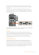
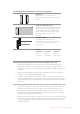

Tracker Interface
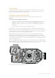
The 10 pin Hirose connector provides a multiplexed output for talkback and tally signals, plus
data such as teleprompter information. This output is commonly used by support crew
operating production equipment such as a camera crane.
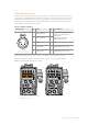
A pinout diagram is provided in this section if you want to build your own cable.
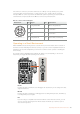
Tracker Output Pinout Diagram
External view Pins Signal I/O Specifications
1 Tracker lef t Out
Tracker output,
-20 dBu unbalanced
2 GND (Talk) – GND for tracker talk
3 GND (Receive/PGM/tally) – GND for receive/PGM/tally
4 Tracker right Out
Tracker output,
-20 dBu unbalanced
5 Unregulated Out +11.9V to 14V dc, 500 mA (max)
6 GND (Unregulated) – GND for unregulated
7 Tracker talk (X) In
Tracker talk 0 dBu /-20 dBu,
high impedance balanced
10 pin hirose
‘tracker’ connector
8 Tracker talk (Y) In
9 G Tally Out
On: GND Off:
High impedance (open collector)
10 R Tally Out
On: GND Off:
High impedance (open collector)
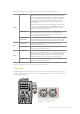
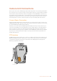
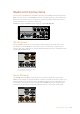
DC Connection
You can power additional accessories, for example an external monitor, via the DC out
connector.
The DC out connector lets you power D-Tap Output
additional accessories, such as a monitor
or external recording equipment
18
9
2
3
7
6
10
45
POWER
RET 1
1 3
2
RET 2 LIGHT
FOCUS
REC
IRIS
TALLY FIBER
1 3
2
PGM 1
MIC
ON
OFF ENG
PROD
INCOM
INTERCOM 1
PGM 2
ON
OFF
PGM 1
MIC
ON
OFF ENG
PROD
INCOM
INTERCOM 2
PGM 2
TRACKER DC OUT
SDI OUT
1
2
3
4
5
1
2
3
4
5
1
2
21
3
LINE MIC
+48V
OFF
AES/EBU
LINE MIC
+48V
OFF
AES/EBU
PTZ
RET 1 RET 2 CALL
12V OUT
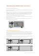
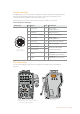
158Camera Unit Connections