
User's Manual
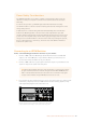
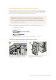
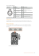

Headset XLR Pinout Diagram
External view Pins Signal I/O Specifications
5-pin XLR
‘headset’ connector
1 Intercom MIC (Y) In
Carbon (-20 dBu, unbalanced)
Dynamic (-60 dBu, balanced/
unbalanced)
Manual (-20/-40/-60 dBu, balanced/
unbalanced)
2 Intercom MIC (X) In
3 GND – GND
4 Intercom left Out 11 dBu (VR Max, 250 Ω Load)
5 Intercom right Out 11 dBu (VR Max, 250 Ω Load)
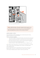
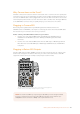
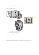
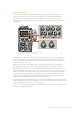
Using Tally
The tally indicator on the front of the panel, provides a traditional tally indicator with red for
program and green for preview, so that you know when the camera you are operating is on air.
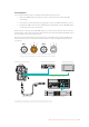
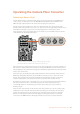
Status Indicators
The 'power', 'tally' and ‘fiber' status LEDs at the top of the converter will illuminate different
colors depending on the status of the unit. When the fiber cable is unplugged, no lights are
illuminated.
The status LEDs will illuminate different colors
to let you know the status of the unit
1
2
3
5
4
POWER
RET 1
1 3
2
RET 2 LIGHT
FOCUS
REC
IRIS
TALLY FIBER
1 3
2
PGM 1
MIC
ON
OFF ENG
PROD
INCOM
INTERCOM 1
PGM 2
ON
OFF
PGM 1
MIC
ON
OFF ENG
PROD
INCOM
INTERCOM 2
PGM 2
TRACKER DC OUT
SDI OUT
1
2
3
4
5
1
2
3
4
5
1
2
21
3
LINE MIC
+48V
OFF
AES/EBU
LINE MIC
+48V
OFF
AES/EBU
POWER TALLY FIBER
150Operating the Camera Fiber Converter