
User's Manual
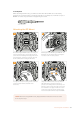

PTZ Interface
Both the studio unit and camera unit has a 9 pin DE-9 connector so you can connect a PTZ
controller at the studio end, and the remote head at the camera end. The PTZ commands are
embedded in the SDI signal connected between the units via the SMPTE fiber cable.
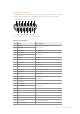
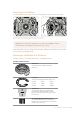
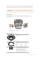
PTZ Interface Pinout Diagram
External view Pins Signal
1 GND
2 RS422 Tx-
3 RS422 Rx+
4 GND
5 N/C
6 GND
7 RS422 Tx+
8 RS422 Rx-
9-pin ‘PTZ’ connector 9 GND
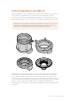
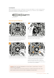
Audio Outputs
The four XLR audio outputs on the studio unit give you the option to output the audio plugged
into inputs 1 and 2 from your URSA Broadcast camera, and the two XLR audio inputs on the
camera unit.
Outputs 1 and 2 on the studio unit correspond to XLR inputs 1 and 2 on URSA Broadcast.
Outputs 3 and 4 on the studio unit correspond to XLR inputs 1 and 2 on the Blackmagic Camera
Fiber Converter.
1
2
8
9
6
7
3
4
5
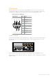
RETURN IN
1 2 3
OUT
OUT
IN
1 2 3 4
AC IN
PTZ
AUDIO ANALOG OUT
INTERCOM / TALLY
ETHERNET
12G DIGITAL I/OOPTICAL I/O REF
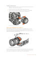
163Studio Unit Connections