
User's Manual

Talkback Interface
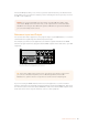
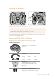
The DB-25 intercom and tally connector lets you connect to third party intercom and tally
systems. A pin out diagram is provided below if you need to build a custom cable.
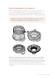
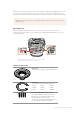
The external view of the 25 pin ‘intercom/tally’ connector
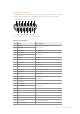
Talkback Pinout Diagram
Pins Signal Specifications
1 ENG(R) IN+
Engineering channel input
0dBu balanced
2 ENG(R) IN-
3 ENG GND GND for ENG
4 ENG(T) OUT +
Engineering channel output
0dBu balanced
5 ENG(T) OUT -
6 PGM IN+ -20dBu
7 PGM IN- -20dBu
8 PGM GND -20dBu
9 GND GND for aux
10 N/C –
11 Red Tally IN On = 5-24Vdc, Off= 0Vdc
12 Red Tally GND –
13 GND Chassis GND
14 PROD(R) IN+
Production channel input
0dBu balanced
15 PROD(R) IN-
16 PROD GND –
17 PROD(T) OUT+
Production channel output
0dBu balanced
18 PROD(T) OUT-
19 N/C –
20 N/C –
21 N/C –
22 N/C –
23 N/C –
24 Green Tally IN On = 5-24Vdc, Off= 0Vdc
25 Green Tally GND –
1
2
24
25
22
23
20
21
18
19
16
17
14
15
3
4
5
6
7
8
9
10
11
12
13
162Studio Unit Connections