
User's Manual
ATEM Broadcast Panel Button Mapping and Button Brightness Level
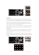
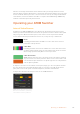
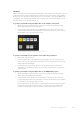
Button Mapping on ATEM Broadcast Panels is easy. On the ATEM Broadcast Panel, go to the
System Control block and press PANEL SETUP followed by BUTTON MAP. Once in the button
map menu, you will notice the System Control window shows a Button number and an Input
number. Turn the knob under Selected Button to select the desired button which you want to
associate with an input. You can do the same thing by selecting the desired button in the
Select row. The buttons in the Select row correspond to the buttons directly below them in the
Preview and Program rows. Next, turn the knob under Selected Input to set an input for the
selected button. Choose another button you wish to map and repeat until all the buttons are
mapped with desired inputs.
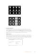
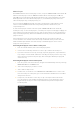
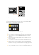
If you want to change the brightness of the buttons, press the BUTTON LEVEL button and
rotate the knob under Brightness until the desired brightness level is seen.
Once you have configured all the button settings, press the SAVE button to save the new
button map and brightness level, or REVERT to discard changes.
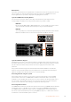
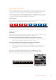
Controlling Two ATEM Switchers
The ATEM 2 M/E Broadcast Panel can be used to control any dual combination of the following
ATEM switchers simultaneously: ATEM 1 M/E Production Switcher, ATEM Television Studio and
ATEM Production Studio 4K models.
The M/E 1 block is the main control block and has a few more settings that can be useful for an
ATEM 1 M/E Production Switcher, or ATEM Production Studio 4K models. To use these additional
settings assign an ATEM Production Studio 4K or 1 M/E Production Switcher to the lower block
of your ATEM 2 M/E Broadcast Panel. If both of your switchers are of the same model, it doesn’t
matter which one you assign to the M/E 1 and M/E 2 blocks.
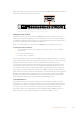
However, if you need quick access to switch auxiliary outputs using the panel buttons,
we suggest assigning System Control M/E 2 to the ATEM Production Studio 4K models or
M/EProduction Switchers. This will let you take advantage of the Aux buttons which only
appear in the M/E 2 block.
If using the default IP settings when using two switchers on the same network, their IP address
will initially be the same, i.e. 192.168.10.240. You should change one of them to 192.168.10.241, or
use an IP address somewhere in the 192.168.10.24_ range to keep all your switchers neatly
together. Please follow the steps detailed in the earlier section “Changing the Switcher
NetworkSettings”.
When connecting the ATEM 2 M/E Broadcast Panel to two switchers, you need to change the
switcher IP on one of the system control blocks to connect to the switcher whose IP address
you have just changed. By default the System Control M/E 1 block connects to 192.168.10.240
and so you will only need to change the System Control M/E 2 block if you are using
default settings.
To set network location of multiple switchers on the ATEM 2 M/E Broadcast Panel, simply
follow these steps for each System Control M/E block:
1 When there is no communication with the switcher, the NETWRK SETUP menu will
appear on the broadcast panel system control. Select the NETWRK SETUP menu
button. If there is communication with a switcher, hold down SHIFT and DEST SHIFT
and select the NETWRK SETUP button.
2 Select the SWITCHR IP menu button and use the knobs or the numeric keypad to edit
each field as required.
3 When a field is changed, SAVE and REVERT menu buttons become available.
Select SAVE to save the changed IP address. The system control display will show
it is connecting to the switcher and will display the model of switcher once it has
successfully connected.
135Using ATEM Hardware Panels